RGB "Bayer" Color and MicroLenses
来源:互联网 发布:党训网络课程心得体会 编辑:程序博客网 时间:2024/05/16 04:47
前言:最近在搞摄像头,出来的图像是bayer pattern的格式。这是啥东西?原来图像sensor每一个点用一个单色表示,最后显示给最终用户时则利用周围的点合成RGB彩色点!
origin:http://www.siliconimaging.com/RGB%20Bayer.htm
RGB "Bayer" Colorand MicroLenses
Bayercolor filter array is a popular format for digital acquisition of color images[1]. The pattern of the color filters is shown below. Half of the total numberof pixels are green (G), while a quarter of the total number is assigned to bothred (R) and blue (B).
G
R
G
R
B
G
B
G
G
R
G
R
B
G
B
G
In order to obtain this colorinformation, the color imagesensor is covered with either a red, a green, or a blue filter, in a repeating pattern. This pattern, or sequence, of filters can vary, but the widelyadopted “Bayer” pattern, which was invented at Kodak, is a repeating2x2 arrangement.
Photographs& Text adapted from Photobit
When the image sensor is read out, line by line, the pixel sequence comes outGRGRGR, etc., and then the alternate line sequence is BGBGBG, etc. This outputis called sequential RGB (or sRGB).
Sinceeach pixel has been made sensitive only to one color (one spectral band), theoverall sensitivity of a color image sensor is lower than a monochrome(panchromatic) sensor, and in fact is typically 3x less sensitive. As a result,monochrome sensors are better for low-light applications, such as securitycameras. (It is also why human eyes switch to black and white mode in the dark).
MicroLenses
Microlenses and a metal opaque layer above the silicon funnel light to thephoto-sensitive portion of each pixel. On their way, the photons of light passthrough a color filter array (CFA) where the process begins of obtaining colorfrom the inherently “monochrome” chip. (Actually, “panchromatic” is anapter term, since sensors respond across the spectrum; the word monochrome comesfrom television use and refers to black and white).
WhiteBalance, Bayer Interpolation and Color matrix Processing
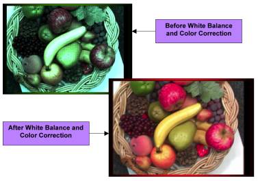
WhiteBalance and Color Correction are processing operations performed to ensureproper color fidelity in a captured digital camera image. In digital cameras anarray of light detectors with color filters over them is used to detect andcapture the image. This sensor does not detect light exactly as the human eyedoes, and so some processing or correction of the detected image isnecessary to ensure that the final image realistically represents the colors ofthe original scene.
G
R
G
R
B
G
B
G
G
R
G
R
B
G
B
G
Each pixel onlyrepresents a portion of the color spectrum and must be interpolated to obtain anRGB value per pixel. The Bayer color filter array (CFA) pattern, shown above, is a popular formatfor digital acquisition of color images [1]. Half of the total number of pixelsare green (G), while a quarter of the total number is assigned to both red (R)and blue (B).
Thisnote describes conversions from Bayer format data to RGB and between RGB and YUV(YCrCb)color spaces. We also discuss two color processing operations (white balance andcolor correction) in the RGB domain, and derive the corresponding operations inthe YUV domain. Using derived operations in the YUV domain, one can performwhite balance and color correction directly in the YUV domain, without switchingback to the RGB domain.
1.) White Balance & BayerInterpolation
Thefirst step in processing the raw pixel data is to perform a white balanceoperation. A white object will haveequal values of reflectivity for each primary color: ie:
R= G = B
Animage of a white object can be captured and its histogram analyzed. The color channel that has the highest level is set as thetarget mean and the remaining two channels are increased with a gain multiplierto match. For example, if Greenchannel has the highest mean, gain ‘a’ is applied to Red and gain ‘b’ isapplied to Blue.
G’= R’a = bB’
TheWhite Balance will vary, based on the color lighting source (Sunlight,Fluorescent, Tungsten) applied to the object and the amount of each colorcomponent within it. A full colornatural scene can also be processed in the same fashion. This “Gray World” method assumes that the world is gray and thedistribution of primaries color will be equal.
The“White Patch” method attempts to locate the objects that are truly white,within the scene; by assuming the whites pixels are also the brightest (I =R+G+B). Then, only the toppercentage intensity pixels are included in the calculation of means, whileexcluding any pixels that may have any channel that is saturated.
BayerInterpolation
To convert an image from the bayer format toan RGB per pixel format, we need to interpolate the two missing color values ineach pixel. Several standard interpolation methods (nearest neighbor, linear,cubic, cubic spline, etc.) were evaluated on this problem in [2]. The authorshave measured interpolation accuracy as well as the speed of the method andconcluded that the best performance is achieved by a correlation-adjustedversion of the linear interpolation. The suggested method is presented here.
Interpolating red and blue components
G
B
G
R
G
R
G
B
G
(a)
G
R
G
B
GB
G
R
G
(b)
B
G
B
G
R
G
B
G
B
(c)
R
G
R
G
B
G
R
G
R
(d)
Figure1: Four possible cases for interpolating R and B components
As suggested in [2], R and B values areinterpolated linearly from the nearest neighbors of the same color. There arefour are possible cases, as shown in Figure 1. When interpolating the missingvalues of R and B on a green pixel, as in Figure 1 (a) and (b), we take theaverage values of the two nearest neighbors of the same color. For example, inFigure 1 (a), the value for the blue component on a shaded G pixel will be theaverage of the blue pixels above and below the G pixel, while the value for thered component will be the average of the two red pixels to the left and right ofthe G pixel.
Figure 1 (c) shows the case when the value ofthe blue component is to be interpolated for an R pixel. In such case, we takethe average of the four nearest blue pixels cornering the R pixel. Similarly, todetermine the value of the red component on a B pixel in Figure 2 (d) we takethe average of the four nearest red pixels cornering the B pixel.
Interpolating the green component
By [2],green component is adaptively interpolated from a pair of nearest neighbors. Toillustrate the procedure, consider two possible cases in Figure 2.
R1
G1
R4
G4
R
G2
R2
G3
R3
(a)
B1
G1
B4
G4
B
G2
B2
G3
B3
(b)
Figure2: Two possible cases for interpolating G component
InFigure 2 (a), the value of the green component is to be interpolated on an Rpixel. The value used for the G component here is
In other words, we take into account thecorrelation in the red component to adapt the interpolation method. If thedifference between R1 and R3 is smaller than thedifference between R2 and R4, indicating that thecorrelation is stronger in the vertical direction, we use the average of thevertical neighbors G1 and G3 to interpolate the requiredvalue. If the horizontal correlation is larger, we use horizontal neighbors. Ifneither direction dominates the correlation, we use all four neighbors.
Similarly, for Figure 2 (b) we will have
Toconclude this section, note that if the speed of execution is the issue, one cansafely use simple linear interpolation of the green component from the fournearest neighbors, without any adaptation
![]()
According to [2], this method of interpolation executes twice as fast asthe adaptive method, and achieves only slightly worse performance on realimages. For even fast updates onlytwo of the four green values are averaged. However, this method displays false color on edges or zipper artifacts.
Color Saturation Matrix
The operationfor saturation can be applied at the same time as the color correction matrix. Unlike the color correction matrix, the saturation matrix does not rotatethe vectors in the color wheel:
[m00 m01 m02] [ R ]
[m10 m11 m12] * [ G ]
[m20 m21 m22] [ B ]
m00 = 0.299 + 0.701*K
m01 = 0.587 * (1-K)
m02 = 0.114 * (1-K)
m10 = 0.299 * (1-K)
m11 = 0.587 + 0.413*K
m12 = 0.114 * (1-K)
m20 = 0.299 * (1-K)
m21 = 0.587 * (1-K)
m22 = 0.114 + 0.886*K
Kis the saturation factor
K=1 means no change
K > 1 increases saturation
0<K<1 decreases saturation, K=0produces B&W , K<0 invertscolor
A sampletable of matrix values are calculated and shown below:
Saturation
Saturation
Saturation
Saturation
1
1.7
1.9
2
R’ =
+R*
1.0
1.4907
1.6309
1.701
+G*
0
-0.4109
-0.5283
-0.587
+B*
0
-0.0798
-0.1026
-0.114
G’ =
+R*
0
-0.2093
-0.2691
-0.299
+G*
1.0
1.2891
1.3717
1.413
+B*
0
-0.0798
-0.1026
-0.114
B’ =
+R*
0
-0.2093
-0.2691
-0.299
+G*
0
-0.4109
-0.5283
-0.587
+B*
1.0
1.6202
1.7974
1.886
The saturated image can be further processed with an additional colorcorrection matrix to compensate for cross-talk induced by the micro-lens andcolor filter process, lighting and temperature effects. The combination matrix ([color correction matrix] * [saturation matrix]) results in a closer to true world colorrepresentation, but an increase in noise. Typically,the blue pixel has the lowest pixel response and the highest Crosstalk from theGreen and Red light. The resultingnoise after matrix operation is a high degree of blue noise.
Amonochrome image can now be easily obtained from a color image by settingK=0
m00 = 0.299
m01 = 0.587
m02 = 0.114
m10 = 0.299
m11 = 0.587
m12 = 0.114
m20 = 0.299
m21 = 0.587
m22 = 0.114
2. Conversion between RGB and YUV
We give two commonly used forms ofequations for conversion between RGB and YUV formats. The first one isrecommended by CCIR [3]
 (2.1)
(2.1)
The second form is used by Intel in theirimage processing library [4], and may be more suitable for implementation:
 (2.2)
(2.2)
In either case, resulting values ofY, U andV should be clipped to fit the appropriate range for the YUV format (e.g.[0,255] for a 24-bit YUV format). The inverse conversion may be accomplished by:
 (2.3)
(2.3)
3. White balance operation in RGB and YUV domains
The white balance operation is defined as again correction for red, green and blue components by gain factorsAR,AG and AB, respectively, i.e.
 (3.1)
(3.1)
The new (white-balanced) values for red, green and blueareRwb, Gwb and Bwb. Toderive the equivalent form of this operation in the YUV domain, we proceed asfollows. First, write equation (2.1) as
![]() (3.2)
(3.2)
where ![]() is the vector in the RGB space,
is the vector in the RGB space,![]() is the corresponding vector in theYUV space,
is the corresponding vector in theYUV space,![]() , andC is the appropriate matrix of conversion coefficients. Similarly,(3.1) can be written as
, andC is the appropriate matrix of conversion coefficients. Similarly,(3.1) can be written as
![]() (3.3)
(3.3)
where ![]() is the vector in the RGB spacemodified by white balance operation (2.4), and
is the vector in the RGB spacemodified by white balance operation (2.4), and![]() . We want to determine what is the corresponding vector
. We want to determine what is the corresponding vector![]() in the YUV domain, without having to revert back to the RGB domain. Vector
in the YUV domain, without having to revert back to the RGB domain. Vector![]() is found by substituting
is found by substituting![]() forx in (3.2)
forx in (3.2)
![]() .
.
Let ![]() , so that
, so that![]() . Then
. Then![]() . Substitute this expression forx back into (3.2) to obtain:
. Substitute this expression forx back into (3.2) to obtain:
![]() (3.4)
(3.4)
This equation provides the connection betweeny and![]() without involvingx or
without involvingx or ![]() (i.e. without going back to the RGBdomain). Manipulating (3.4) and using the fact that for nonsingular matrices
(i.e. without going back to the RGBdomain). Manipulating (3.4) and using the fact that for nonsingular matrices![]() [5], we get that white balanceoperation in the YUV domain is
[5], we get that white balanceoperation in the YUV domain is
![]() (3.5)
(3.5)
Expressing components of ![]() from (3.5) we get
from (3.5) we get
Terms with leading coefficient less than 10-3 have been dropped.
References
[1] B. E. Bayer, Color imaging array, US Patent No. 3971065.
[2] T. Sakamoto, C. Nakanishi and T. Hase, “Software pixel interpolationfor digital still cameras suitable for a 32-bit MCU,”IEEE Trans. ConsumerElectronics, vol. 44, no. 4, November 1998.
{3} http://www.northpoleengineering.com/rgb2yuv.htm
- RGB "Bayer" Color and MicroLenses
- RGB "Bayer" Color and MicroLenses
- RGB "Bayer" Color and MicroLenses, convertion between RGB and YUV
- RGB Bayer Color分析
- RGB Bayer Color分析
- MATLAB图像处理_Bayer图像处理 & RGB Bayer Color分析
- 【VS开发】【图像处理】RGB Bayer Color分析
- Csharp: Winform 顏色選擇器 Color convert RGB and RGB convert Color
- Csharp: Winform 顏色選擇器 Color convert RGB and RGB convert Color
- Bayer Pattern to RGB
- Bayer Pattern to RGB
- Bayer转RGB
- bayer类型转RGB
- Bayer Pattern to RGB
- Bayer图像转RGB
- Bayer to RGB
- Bayer RGB和RGB Raw
- Bayer RGB和RGB Raw
- 年度总结-遇见未知的自己
- 数据库与缓存
- 逻辑混乱--Java web初学,思路梳理
- Hadoop2.7.3 编译 支持5种压缩
- Map.values方法——获取Map集合中的所有键值对象
- RGB "Bayer" Color and MicroLenses
- filter、map、reduce、lambda(Python)
- 如何取得视频流数据?
- WebStorm mac版破解方法
- 登录记住密码
- Spark的安装配置以及初步测试
- Qt5 由.ui文件生成.pro文件和C++文件
- js输出当前时间到指定位置
- java 反射机制