Converting dual fisheye images into a spherical (equirectangular) projection
来源:互联网 发布:java线程池实现方式 编辑:程序博客网 时间:2024/05/24 01:10
Converting dual fisheye images into a spherical (equirectangular) projection
Written by Paul BourkeAugust 2016
The source code implementing the projections below is only available on request for a small fee. It includes a demo application and an invitation to convert an image of your choice to verify the code does what you seek. For more information please contact the author.
Introduction
The following presents one method by which two fisheye images, with sufficient apertures, can be combined to form one spherical (equirectangular) projection. It is one of two main approaches, this is a purely geometric algorithm, the alternative is to detect feature points between the two overlapping fisheye images and perform a warp/blend.
A "fisheye" image is taken to mean a projection defined as a circular fisheye, namely radially symmetric in longitude and with latitude proportional to the radius from the center of the fisheye circle. Most lenses do have some non-linearity and this is a relatively straightforward correction to make. A fisheye is defined for any angle, 180 being the most common but in the context here one requires greater than 180 degrees. The fisheye circle may be smaller than the image frame it is contained in (sensor size) or it may be larger, so the circle is clipped. Both these situations are common for real fisheye images and camera sensors and as such need to be dealt with.
ImplementationThe algorithm described here is tested with a command line utility that accepts various command line option and reads a parameter file describing attributes of the fisheye images. The usage string is as follows.
Usage: dualfish2sphere [options] parameterfileOptions -w n sets the output image size, default: twice fisheye width -a n sets antialiasing level, default: 2 -b n longitude width for blending, default: no blending -d debug mode
The algorithm, as with many of this nature, considers each pixel in the output image and determines the best estimate from the input images. Antialising here is performed using a simple supersampling approach, each pixel in the output image is sampled multiple times at different subpixel positions, the best estimates from the input images are averaged together. For fisheye images greater than 180 degree aperture, the two overlapping halves of their projection into equirectangular space are blended together using a simple linear multiplicative blend function.
The parameter file consists of a series of lines consisting of a keyword and value pair. At the very least the file must contain two IMAGE: keywords, the modifier keywords can appear in any order and apply to the previously defined IMAGE:. Noting that the order in which the rotate keywords appear determines the order in which they are performed. An example parameter file is given below, the meanings of the keywords should be clear. A line starting with a "#" is a comment line, the rest of the line will be ignored. All angles are defined in degrees and all coordinates are defined in pixels.
# left imageIMAGE: sample.tgaRADIUS: 904CENTER: 959 970APERTURE: 190ROTATEZ: -1.2ROTATEX: 0ROTATEY: -90# right imageIMAGE: sample.tgaRADIUS: 904CENTER: 2879 948APERTURE: 189ROTATEX: -2ROTATEY: 90
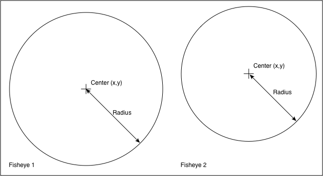
In the above the two fisheye images are assumed to be in the same image, one on the left of the other although the algorithm isn't affected by the order. The software also handles the case where the two fisheyes are located within different files. CENTER: defines the center of the fisheye circle (origin is the top left corner of the image). RADIUS: is the radius of the fisheye circle that matches the given APERTURE:. The conventions for a single file containing two fisheye images is given below.
Note the extreme generality of these defining parameters, the fisheye images need not have the same aperture, radius, or position in the image. This is largely to deal with integrated dual fisheye systems that, in the real world, are rarely perfect. For example the lenses are not always on the same optical axis and there is variation between the optics of any two fisheye lenses.
The various rotation angles provide a mechanism by which corrections can be made to the fisheye camera/lens system, for example if they don't share the same optical axis. The fisheye lens/camera is assumed to be looking down the y axis, so ROTATEY: serves to roll the fisheye. The x axis is assumed to be to the right, so a ROTATEX serves to correct for the fisheye tilt. The z axis is up so ROTATEZ: serves to pan the fisheye. Note the since the algorithm operates in reverse (from the output image to the input fisheye) the rotational transformations act in the reverse order to which they appear in the parameter file.
ExampleThe following example will illustrate the main features of the algorithm implementation. It will be based upon two separate fisheye images, each with an aperture of 210 degrees.
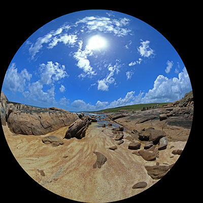
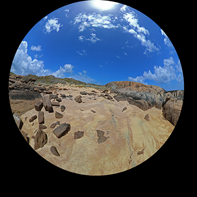
In this somewhat artificial example the left fisheye above is tilted up by 10 degrees. The right fisheye above is rotated clockwise off the optical axis by 5 degrees. The parameter file is given below.
# Example for online example# first fisheyeIMAGE: exampleleft.tgaAPERTURE: 210RADIUS: 1024CENTER: 1024 1124ROTATEX: -10# second fisheyeIMAGE: exampleright.tgaCENTER: 1124 1024RADIUS: 1024APERTURE: 210ROTATEY: -5
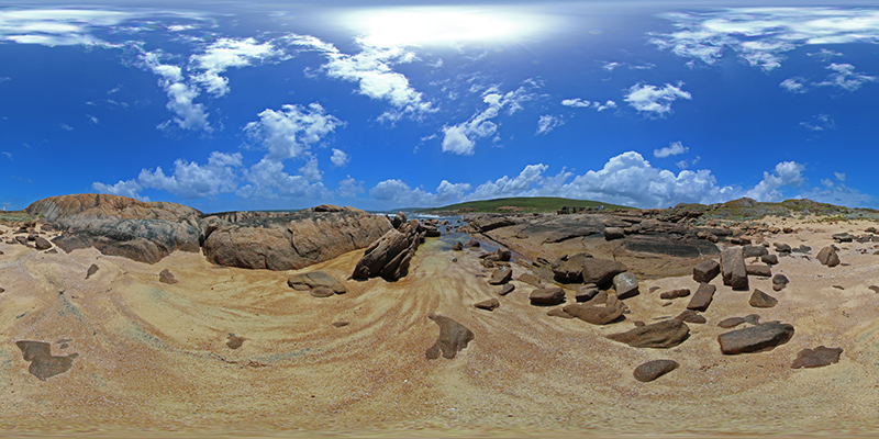
Each fisheye is located in a different part of the image (sensor) plane. The resulting panorama after compensating correctly for these camera/fisheye errors is shown below.
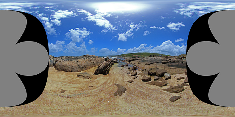
So how does this work? Each fisheye, assuming it has an aperture of at least 180 degrees captures half the visible world, another fisheye pointing in the opposite direction captures the other half. It should therefore be possible to merge the two fisheye images together to form a complete equirectangular projection, which defines the whole visible world. The left fisheye above mapped into equirectangular space is shown below, it fills more than half the equirectangular image because the lens is 210 degrees. Some additional notes and implementation of converting fisheye to equirectangular images can be found here.
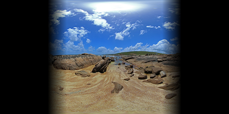
Repeating for the right hand fisheye above gives the following, noting that it generally covers the second half of the equirectangular image and in this case is continuous across the 0 to 360 agle wrap.

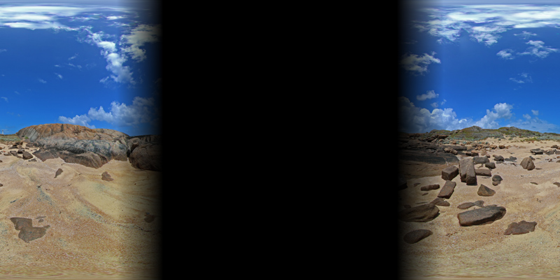
As long as the fisheyes have an aperture greater than 180 degrees there is some image overlap to blend the two halves together. The two images with a blend zone of 15 degrees (75 degrees to 105 degrees) are given below. The final image is achieved by simply adding these on a pixel by pixel basis.
Notes
Fisheye angles of 190 degrees or more are required for a satisfactory blend zone, 10 degrees.
The discussion here does not address the fundamental issues of parallax error in real dual fisheye systems where the nodal points of the lenses do not coincide. A perfect blend can occur at any one distance but not at all distances.
- Converting dual fisheye images into a spherical (equirectangular) projection
- Converting a fisheye image into a panoramic, spherical or perspective projection
- Converting a fisheye image into a panoramic, spherical or perspective projection
- Equirectangular Projection(ERP)
- Dome projection using a spherical mirror
- Storing Images into a Database
- How can I refactor converting this array into a Hash
- Converting between ROS images and OpenCV images
- Adding images into UIScrollview
- Real-Time Direct Dense Matching on Fisheye Images
- Fisheye
- Converting .docx into (.doc, .pdf, .html)
- JAXB - Avoid converting < into < and > into > during Marshalling
- select (SYSDATE - 10) into datevar from dual
- Projection
- JXL : write images and... into excel
- Converting a bitmap to a region
- Converting a List to a DataTable
- Java数据结构与算法之数据结构-逻辑结构-集合(一)------集合类简析
- 亲身体验搭建apache2.4+php-5.6.28集成环境搭建(网上太多坑了。。。搭建2天搞定)
- js对<select><option>操作和jq的选择器
- C#语言中的Using语句块确保资源被释放
- c#页面展示两位小数
- Converting dual fisheye images into a spherical (equirectangular) projection
- Mac安装android studio后卡在building gradle project info的解决方法
- webpack 配置热更新
- spring-security认证过程的分析及自定义登录
- 最受欢迎的12个AI工具、库和平台
- Hadoop全链路监控方案
- 一个程序员浏览器收藏
- 冒泡排序、选择排序、插入排序、快速排序
- 大家好,给你们介绍一下,这是我的....