Different Crossover Cable & Straight Through
来源:互联网 发布:mac如何进入运行程序 编辑:程序博客网 时间:2024/04/29 05:26
Ethernet Crossover Cables Explained
Ethernet crossover cables are most often used in home networks when connecting two ethernet computers without a hub. An Ethernet crossover cable has it's send and receive wires crossed. When using a hub or switch, this is automatically done for you.
Unfortunately some devices like cable and dsl modems have their actual ethernet plugs reversed. This is to allow people to hook up a cable modem to a computer without a special crossover cable. When adding a hub into the mix, the issue can get confusing.
Most modern hubs and switches have what is called an uplink port on them. This is the same kind of 'reversed' port that is on a cable or dsl modem.
This may sound like a confusing issue, but here are some network diagrams that will show when to use a normal ethernet cable and when to use a crossover cable.
GREEN cables represent standard ethernet cables(No Crossover cable needed)
BLUE cables represent CROSSOVER cables(Crossover cable IS needed)
![]()
Note: One port on your hub will usually be 'shared' with the uplink port. Either the uplink port OR the standard port can be used, no both.
Check toward the bottom of this page for great prices on crossover and standard ethernet cables.
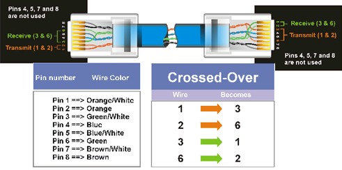
Crossover Ethernet Cable Pinouts:
(Courtesey of linksys...)
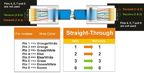
Standard Ethernet Cable Pinouts:
(Courtesey of linksys...)
--------------------------------------Dividing--Line-------------------------------------------
COLOR-CODE STANDARDS
Again, please bear with me... Let's start with simple pin-out diagrams of the two types of UTP Ethernet cables and watch how committees can make a can of worms out of them. Here are the diagrams:

Note that the TX (transmitter) pins are connected to corresponding RX (receiver) pins, plus to plus and minus to minus. And that you must use a crossover cable to connect units with identical interfaces. If you use a straight-through cable, one of the two units must, in effect, perform the cross-over function.
Two wire color-code standards apply: EIA/TIA 568A and EIA/TIA 568B. The codes are commonly depicted with RJ-45 jacks as follows (the view is from the front of the jacks):

If we apply the 568A color code and show all eight wires, our pin-out looks like this:
Note that pins 4, 5, 7, and 8 and the blue and brown pairs are not used in either standard. Quite contrary to what you may read elsewhere, these pins and wires are not used or required to implement 100BASE-TX duplexing--they are just plain wasted.
However, the actual cables are not physically that simple. In the diagrams, the orange pair of wires are not adjacent. The blue pair is upside-down. The right ends match RJ-45 jacks and the left ends do not. If, for example, we invert the left side of the 568A "straight"-thru cable to match a 568A jack--put one 180° twist in the entire cable from end-to-end--and twist together and rearrange the appropriate pairs, we get the following can-of-worms:
This further emphasizes, I hope, the importance of the word "twist" in making network cables which will work. You cannot use an flat-untwisted telephone cable for a network cable. Furthermore, you must use a pair of twisted wires to connect a set of transmitter pins to their corresponding receiver pins. You cannot use a wire from one pair and another wire from a different pair.
Keeping the above principles in mind, we can simplify the diagram for a 568A straight-thru cable by untwisting the wires, except the 180° twist in the entire cable, and bending the ends upward. Likewise, if we exchange the green and orange pairs in the 568A diagram we will get a simplified diagram for a 568B straight-thru cable. If we cross the green and orange pairs in the 568A diagram we will arrive at a simplified diagram for a crossover cable. All three are shown below:
From:
COLOR-CODE STANDARDS
- Different Crossover Cable & Straight Through
- crossover, straight through, roll over, and serial cable .
- rollover,straight-throught,crossover 三种线的比较
- Crossover
- CrossOver
- CrossOver介绍
- 1002 cable cable cable
- HDU6195 cable cable cable
- cable cable cable(水题)
- cable cable cable
- hdu6195 cable cable cable
- HDU6195-cable cable cable
- PATH is different if login with same account but through different way on ubuntu(Not figure out yet)
- different
- HDU 6159 cable cable cable
- HDU6195 cable cable cable 签到
- HDU 6195 cable cable cable
- HDU 6195 cable cable cable
- 如何防止U盘病毒入侵方法
- jquery checkbox 相关操作
- 我是新来的
- 这忧伤,仿佛溪流,仿佛海风,仿佛忧伤划过安静
- openfire及其源码的开发和部署
- Different Crossover Cable & Straight Through
- Eclipse 快捷键
- 2010年2月补丁KB978037造成VisualStudio的Debug控制台无法关闭
- 保证SetForegroundWindow成功
- update Flex TreeGrid
- ASP.NET使用无Cookie的表单认证票据
- 我的10年计算机之路
- oracle 存储过程的基本语法 及注意事项
- 初学数据挖掘