[翻译]Global Descriptor Table-GDT
来源:互联网 发布:windows pe和windows7 编辑:程序博客网 时间:2024/05/17 23:48
全局描述符表(GDT)是 Intel x86 系列处理器(从 80286 开始)所使用的一种数据结构,目的是为了在程序运行期间划分具有不同属性的内存区域,比如:可以运行、可写入等区域的起始地址与访问权限。这些区域被称作段。
全局描述符表除了可以保存段信息外还可以保存其它信息。全局描述符表中的每个表项(描述子)长度为 8-byte,全局描述符表的选择子可以为:任务状态描述子(TSS)、本地描述符表描述子或者调用门描述子。调用门在 x86 不同特权级中转移控制权非常重要,但是现在的操作系统很少使用这种机制。
同时存在的还有局部描述符表(LDT)。局部描述符表用来存储程序内部的段信息,而全局描述符表用来描述全局的段信息。x86 系列的处理器具有一种机制,可以在发生某些事件时自动切换局部描述符表,但是针对全局描述符表却没有这样的机制。
程序可以访问的内存通常被限制在一个段内。在 386 及以后的处理器中,由于 32 位的段内偏移与段大小的原因,有可能使段覆盖全部可寻址的空间,并且相关的段对用户来说也使透明的。
程序如果想使用某个段,需要在全局描述符表或者局部描述符表中找到该段对应的索引。这个索引被称为段选择子。为了使用相应的段,段选择子必须被首先加载到段寄存器。除了可以通过机器指令读取或者设置全局描述符表(还有中断描述符表)的内存地址外,指令所引用的内存地址存在于一个隐式的段,有时有两个。大部分情况下,默认的段寄存器可以通过在地址前面加一个段地址来替换。加载段选择子到段寄存器的过程中,程序会自动读取全局描述符表或者局部描述符表,并将相关信息保存到处理器中。在全局描述符表或者局部描述符表被加载后,对二者的修改并不会起作用,除非重新将相应的表加载到寄存器。
64 位下全局描述符表
全局描述符表在 64 位下仍然是合法可用的。相应的寄存器位数从 48 位扩展到了 80 位,64 位的段选择子是平坦的、无限制的(从 0x0000000000000000 到 0xFFFFFFFFFFFFFFFF)。64 位版本的 Windows 仍然禁止对全局表述附表的 hook 操作,如果进行这种操作会引发一个系统错误。
=========================================================================
386 处理器保护机制的重要方面就是全局描述符表。全局描述符表定义了一些内存区域的基本访问权限。可以使用全局描述符表中一个表项来描述一个段非法访问异常,这样,在进程进行了非法操作时,内核可以有机会终止进程。现代的大部分操作系统使用分页来实现这个机制:这种机制更加通用,给了上层更加大的灵活性。全局描述符表同样可以定义一块内存区域是可执行的,还是普通数据。全局描述符表有能力定义任务状态段(TSS)。TSS 用来实现基于硬件的多任务,这里不讨论。但是需要说明的是 TSS 并不是实现多任务的唯一方法。
GRUB 已经为我们加载了一个全局描述符表,如果我们重写了 GRUB 已经加载了的内存(全局描述符表所占空间),我们会破坏全局描述符表,并会引发一个 “triple fault” 错误。后果是引起机器重启。我们应该在有权限访问的内存中定义自己的全局描述符表,从而避免这个问题。这就需要我们重建全局描述符表,告诉处理器全局描述符表的位置,最后需要重新设置CS, DS, ES, FS, and GS,将其对应到我们自己的全局描述符表。CS 通常被称为代码段寄存器。代码段寄存器可以向处理器提供代码段在全局描述符表中偏移量,同时还提供了当前可执行代码的访问权限。同样,DS 向处理器提供了当前数据的访问权限。ES, FS, GS 只是改变 DS,对我们来说不重要。
全局描述符表是一个每个表项 64 位的表。每个表项定义了可以使用的内存区域的:起始,长度,访问权限。通用规则是:全局描述符表的第一个表项是 0,是一个空的描述符。段寄存器不应该被设置为 0,否则引发一个保护错,保护错是处理器的一种保护机制。保护错与处理器的其它保护机制在 http://www.osdever.net/bkerndev/Docs/isrs.htm 有详细介绍。
每个表项还定义了处理器当前正在运行的代码是在系统层(Ring0)还是在应用程序层(Ring3)。还有其它的 Ring,但是不重要。现在主要的操作系统都只使用 Ring0 与 Ring3。作为一个基本规则:如果应用程序访问 Ring0 ,会引发一个异常。这是为了让应用程序不会使系统崩溃。在全局描述符表部分所涉及的 Ring,主要是定了处理器是否可以执行某些特权指令。某些指令是特权级的,意味着只能在高特权的 Ring 中执行。例如:cli,sti 会禁用或者启用中断。如果允许应用程序使用 cli 与 sti,那它就可以终止内核的运行。
全局描述服表项
7 6 5 4 3 0 P DPL DT Type P - Segment is present? (1 = Yes)DPL - Which Ring (0 to 3)
DT - Descriptor Type
Type - Which type?
7 6 5 4 3 0 G D 0 A Seg Len. 19:16 G - Granularity (0 = 1byte, 1 = 4kbyte)
D - Operand Size (0 = 16bit, 1 = 32-bit)
0 - Always 0
A - Available for System (Always set to 0)
在作为练习的系统内核中,我们会定义一个具有 3 个表项的全局描述符表。为什么 3 个?我们需要一个 'dummy' descriptor,来演示处理的保护特性。我们还需要一个代码段,一个数据段。我们使用 lgdt 指令来让处理器重新加载全局描述符表。使用 lgdt 指令需要一个指针,该指针指向一个 48 位的结构。48 位结构的前 16 位定义了全局描述符表的大小,剩下的 32 位是全局描述符表在内存中的起始地址。
我们可以简单的使用具有 3 个元素的数组来定义全局描述符表。
全局描述符表的一个实现:
#include < system.h >/* Defines a GDT entry. We say packed, because it prevents the* compiler from doing things that it thinks is best: Prevent* compiler "optimization" by packing */struct gdt_entry{ unsigned short limit_low; unsigned short base_low; unsigned char base_middle; unsigned char access; unsigned char granularity; unsigned char base_high;} __attribute__((packed));/* Special pointer which includes the limit: The max bytes* taken up by the GDT, minus 1. Again, this NEEDS to be packed */struct gdt_ptr{ unsigned short limit; unsigned int base;} __attribute__((packed));/* Our GDT, with 3 entries, and finally our special GDT pointer */struct gdt_entry gdt[3];struct gdt_ptr gp;/* This will be a function in start.asm. We use this to properly* reload the new segment registers */extern void gdt_flush();
; This will set up our new segment registers. We need to do; something special in order to set CS. We do what is called a; far jump. A jump that includes a segment as well as an offset.; This is declared in C as 'extern void gdt_flush();'global _gdt_flush ; Allows the C code to link to thisextern _gp ; Says that '_gp' is in another file_gdt_flush: lgdt [_gp] ; Load the GDT with our '_gp' which is a special pointer mov ax, 0x10 ; 0x10 is the offset in the GDT to our data segment mov ds, ax mov es, ax mov fs, ax mov gs, ax mov ss, ax jmp 0x08:flush2 ; 0x08 is the offset to our code segment: Far jump!flush2: ret ; Returns back to the C code!
/* Setup a descriptor in the Global Descriptor Table */void gdt_set_gate(int num, unsigned long base, unsigned long limit, unsigned char access, unsigned char gran){ /* Setup the descriptor base address */ gdt[num].base_low = (base & 0xFFFF); gdt[num].base_middle = (base >> 16) & 0xFF; gdt[num].base_high = (base >> 24) & 0xFF; /* Setup the descriptor limits */ gdt[num].limit_low = (limit & 0xFFFF); gdt[num].granularity = ((limit >> 16) & 0x0F); /* Finally, set up the granularity and access flags */ gdt[num].granularity |= (gran & 0xF0); gdt[num].access = access;}/* Should be called by main. This will setup the special GDT* pointer, set up the first 3 entries in our GDT, and then* finally call gdt_flush() in our assembler file in order* to tell the processor where the new GDT is and update the* new segment registers */void gdt_install(){ /* Setup the GDT pointer and limit */ gp.limit = (sizeof(struct gdt_entry) * 3) - 1; gp.base = &gdt; /* Our NULL descriptor */ gdt_set_gate(0, 0, 0, 0, 0); /* The second entry is our Code Segment. The base address * is 0, the limit is 4GBytes, it uses 4KByte granularity, * uses 32-bit opcodes, and is a Code Segment descriptor. * Please check the table above in the tutorial in order * to see exactly what each value means */ gdt_set_gate(1, 0, 0xFFFFFFFF, 0x9A, 0xCF); /* The third entry is our Data Segment. It's EXACTLY the * same as our code segment, but the descriptor type in * this entry's access byte says it's a Data Segment */ gdt_set_gate(2, 0, 0xFFFFFFFF, 0x92, 0xCF); /* Flush out the old GDT and install the new changes! */ gdt_flush();}
=========================================================================
在 Intel 架构的处理器中,更确切的说是在保护模式下,内存管理与中断服务程序的控制是通过描述符表(tables of descriptors)来实现的。每个描述符的表项保存了处理器在某个时间要用的信息(例如:服务例程,任务,代码,数据等等)。如果你试着为段寄存器设置一个新值,处理器会进行关于安全与访问控制的检查。一旦通过检查,处理器会在内部寄存器中缓存这些值。
Intel 系列的处理器定义了三张表:中断描述符表,全局表述附表,局部描述符表。可以通过 LIDT,LGDT,LLDT 三个指令来加载这三张表。在大多数情况下,系统只是在启动时告诉处理器这三张表的位置,然后在以后的运行过程中通过指针来读取或者修改这三张表。
全局描述符表中应该存放什么信息?
如果完成的话,表中应该保存如下信息:
× 处理器从不引用的空指针。如果不设置,某些模拟器会抱怨缺少 limit exception。某些情况下,只是在这个位置保存指向全局描述符表自身的指针。
× 代码段描述子。对于内核来说,这个表项的类型为 0x9A。
× 数据段描述子。因为无法向代码段中写数据,因此需要添加数据段,类型为 0x92。
× 任务状态描述子。最好为这个段保留一定空间。
× 其它描述子空间。例如:用户界别(user-level),局部描述符表,更多的任务状态描述子。
Sysenter/Sysexit
如果你想使用 Intel 的 Sysenter/Sysexit 例程,那么全局描述符表必须这样组织:
× 前面提到的一些段(NULL 描述子,kernel stuff,等等)
× DPL0 代码段描述子。Sysenter 使用。
× DPL0 数据段描述子。Sysenter 栈使用。
× DPL3 代码段描述子。Sysexit 后需要执行的代码。
× DPL3 数据段描述子。在 Sysexit 后,用户态的栈。
× 其它描述子。
DPL0 代码段的内容被加载到 MSR。其它值通过这个值来计算。具体参考 Intel 的手册。
平坦模式初始化(
Flat Setup)如果想使用不需要翻译(查表,转换)的 4 G 空间:
GDT[0] = {.base=0, .limit=0, .type=0}; // Selector 0x00 cannot be usedGDT[1] = {.base=0, .limit=0xffffffff, .type=0x9A}; // Selector 0x08 will be our codeGDT[2] = {.base=0, .limit=0xffffffff, .type=0x92}; // Selector 0x10 will be our dataGDT[3] = {.base=&myTss, .limit=sizeof(myTss), .type=0x89}; // You can use LTR(0x18)
微内核模式初始化(Small Kernel Setup)
如果基于某种原因需要将代码段与数据段分开,并且假设每个有 4M 空间,起始与 4M。
GDT[0] = {.base=0, .limit=0, .type=0}; // Selector 0x00 cannot be usedGDT[1] = {.base=0x04000000, .limit=0x03ffffff, .type=0x9A}; // Selector 0x08 will be our codeGDT[2] = {.base=0x08000000, .limit=0x03ffffff, .type=0x92}; // Selector 0x10 will be our dataGDT[3] = {.base=&myTss, .limit=sizeof(myTss), .type=0x89}; // You can use LTR(0x18)
这意味着在物理内存 4M 空间内的信息可以从 CS:0 开始访问。物理内存 8M 空间内的信息可以从 DS:0 开始访问。这不是一个好的设计。
具体应该怎么操作呢?
禁用中断
如果中断处于开启状态,就禁用中断,否则是自找麻烦。
向表格中填充数据
我们现在还没有给出 GDT[] 的具体结构。这是有目的的。描述子的实际结构因为某种原因有点混乱。地址被分成三个部分,无法进行编码限制,同时还要正确设置很多标志位。
/** * /param target A pointer to the 8-byte GDT entry * /param source An arbitrary structure describing the GDT entry */void encodeGdtEntry(uint8_t *target, struct GDT source){ // Check the limit to make sure that it can be encoded if ((source.limit > 65536) && (source.limit & 0xFFF) != 0xFFF)) { kerror("You can't do that!"); } if (source.limit > 65536) { // Adjust granularity if required source.limit = source.limit >> 12; target[6] = 0xC0; } else { target[6] = 0x40; } // Encode the limit target[0] = source.limit & 0xFF; target[1] = (source.limit >> 8) & 0xFF; target[6] |= (source.limit >> 16) & 0xF; // Encode the base target[2] = source.base & 0xFF; target[3] = (source.base >> 8) & 0xFF; target[4] = (source.base >> 16) & 0xFF; target[7] = (source.base >> 24) & 0xFF; // And... Type target[5] = source.type;}
告诉处理器去哪里寻找全局表述附表
使用 LGDT 指令设置。
对于实模式
线性地址是通过段基址右移 4 位,然后加上段内偏移获得的。假设 GDT 和 GDT_end 两个符号在当前的数据段:
gdtr DW 0 ; For limit storage DD 0 ; For base storage setGdt: XOR EAX, EAX MOV AX, DS SHL EAX, 4 ADD EAX, ''GDT'' MOV [gdtr + 2], eax MOV EAX, ''GDT_end'' SUB EAX, ''GDT'' MOV [gdtr], AX LGDT [gdtr] RET
平坦的保护模式下
平坦意味着数据段的地址从 0 开始。如果通过 GRUB 进行引导就是这种情况。假设你调用 setGdt(GDT, sizeof(GDT)): gdtr DW 0 ; For limit storage DD 0 ; For base storage setGdt: MOV EAX, [esp + 4] MOV [gdtr + 2], EAX MOV AX, [ESP + 8] MOV [gdtr], AX LGDT [gdtr] RET
非平坦的保护模式
如果数据段的起始地址不是 0,就属于这种模式。
需要:
"MOV EAX, ..."
"ADD EAX, base_of_your_data_segment_which_you_should_know"
"MOV ..., EAX"
重新设置各个段寄存器
无论怎么修改全局描述符表,如果没有设置各个段寄存器,修改不会起作用。
reloadSegments: ; Reload CS register containing code selector: JMP 0x08:reload_CS ; 0x08 points at the new code selector.reload_CS: ; Reload data segment registers: MOV AX, 0x10 ; 0x10 points at the new data selector MOV DS, AX MOV ES, AX MOV FS, AX MOV GS, AX MOV SS, AX RET
为什么局部描述符表很特别?
像全局描述符表一样,局部描述符表也包含关于内存区域的描述子,但是这些描述子被称作门。每个任务都可以有自己的局部描述符表,当使用硬件任务切换时,处理器会自动切换到正确的局部描述符表。
因为对于每个任务来说,局部描述符表可能不同,局部描述符表不是一个保存系统相关信息的地方,例如:任务状态描述子,或者其它局部描述符表,而这些是全局描述符表的责任。因为全局表述附表经常改变,因此他的设置与全局描述符表还有中断描述符表有些不同。局部描述符表不是通过直接设置其地址与大小完成的,那些信息被保存在了全局描述符表(选择子的类型是 LDT), 对应选择子的信息如下:
GDTR (base + limit) +-- GDT ------------+ | |SELECTOR ---> [LDT descriptor ]----> LDTR (base + limit) | | +-- LDT ------------+ | | | | ... ... ... ... +-------------------+ +-------------------+在 386+处理器的分页机制下,局部描述符表已经没用了。已经没有必要设置多个局部描述符选择子,因此对于系统开发来说可以忽略处理器的这个特性了。
什么是中断描述符表?是否需要中断描述符表?
参考:http://wiki.osdev.org/index.php?title=Interrupts_for_dummies&action=edit
=========================================================================
GDT 的加载使用 LDGT 指令。GDT 的结构如下:
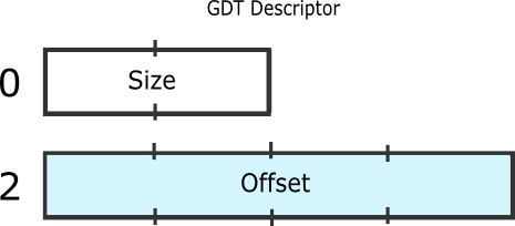
offset 是表格自身的虚拟地址。size 为表格的大小减一。原因是:size 的最大值是 65535,而全局描述符表对打可以还有 65536 byte(8192 个表项)。每个表项 8byte,其复杂的结构如下:
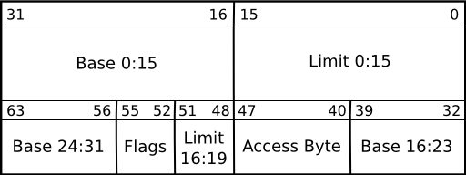
What "Limit 0:15" means is that the field contains bits 0-15 of the limit value. The base is a 32 bit value containing the linear address where the segment begins. The limit, a 20 bit value, tells the maximum addressable unit (either in 1 byte units, or in pages). Hence, if you choose page granularity (4 KiB) and set the limit value to 0xFFFFF the segment will span the full 4 GiB address space. Here is the structure of the access byte and flags:
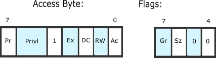
The bit fields are:
- Pr: Present bit. This must be 1 for all valid selectors.
- Privl: Privilege, 2 bits. Contains the ring level, 0 = highest (kernel), 3 = lowest (user applications).
- Ex: Executable bit. If 1 code in this segment can be executed, ie. a code selector. If 0 it is a data selector.
- DC: Direction bit/Conforming bit.
- Direction bit for data selectors: Tells the direction. 0 the segment grows up. 1 the segment grows down, ie. the offset has to be greater than the base.
- Conforming bit for code selectors:
- If 1 code in this segment can be executed from an equal or lower privilege level. For example, code in ring 3 can far-jump to conforming code in a ring 2 segment. The privl-bits represent the highest privilege level that is allowed to execute the segment. For example, code in ring 0 cannot far-jump to a conforming code segment with privl==0x2, while code in ring 2 and 3 can. Note that the privilege level remains the same, ie. a far-jump form ring 3 to a privl==2-segment remains in ring 3 after the jump.
- If 0 code in this segment can only be executed from the ring set in privl.
- RW: Readable bit/Writable bit.
- Readable bit for code selectors: Whether read access for this segment is allowed. Write access is never allowed for code segments.
- Writable bit for data selectors: Whether write access for this segment is allowed. Read access is always allowed for data segments.
- Ac: Accessed bit. Just set to 0. The CPU sets this to 1 when the segment is accessed.
- Gr: Granularity bit. If 0 the limit is in 1 B blocks (byte granularity), if 1 the limit is in 4 KiB blocks (page granularity).
- Sz: Size bit. If 0 the selector defines 16 bit protected mode. If 1 it defines 32 bit protected mode. You can have both 16 bit and 32 bit selectors at once.
- [翻译]Global Descriptor Table-GDT
- GDT--Global Descriptor Table
- GDT(Global Descriptor Table)全局描述符表
- GDT(Global Descriptor Table)全局描述符表
- [翻译]Interrupt Descriptor Table–IDT
- INTERRUPT DESCRIPTOR TABLE (IDT)
- Intel为何不使用GDT中的第一个Descriptor?
- 段描述表Descriptor Table
- GLOBAL TEMPORARY TABLE
- GLOBAL TEMPORARY TABLE (zt)
- global temporary table
- global temporary table index
- GLOBAL TEMPORARY TABLE
- 查找global temporary table
- GLOBAL TEMPORARY TABLE
- GLOBAL TEMPORARY TABLE
- Oracle GLOBAL TEMPORARY TABLE
- GLOBAL TEMPORARY TABLE
- JAVA核心技术笔记1--基础知识
- Advanced Perl Programming 读书笔记
- VMware下ghost安装XP后无法从硬盘启动的问题
- MoinMoin在Window7上安装
- 模式匹配之Boyer-Moore算法
- [翻译]Global Descriptor Table-GDT
- 关于thinkpad安装windows7屏幕亮度调节的解决方案
- SqlServer2005T-Sql增强
- Android QQMusic 设计实录
- ASP.NET迈出重要一步!
- POJ 1330 LCA问题
- PCB线宽与电流的关系
- 转 怎样才算熟练掌握数据结构、常用算法?
- TD视频连接