实例解析linux内核I2C体系结构
来源:互联网 发布:2017淘宝去同款软件 编辑:程序博客网 时间:2024/04/27 21:58
实例解析linux内核I2C体系结构
作者:刘洪涛,华清远见嵌入式学院讲师。
一、概述
谈到在linux系统下编写I2C驱动,目前主要有两种方式,一种是把I2C设备当作一个普通的字符设备来处理,另一种是利用linux I2C驱动体系结构来完成。下面比较下这两种驱动。
第一种方法的好处(对应第二种方法的劣势)有:
● 思路比较直接,不需要花时间去了解linux内核中复杂的I2C子系统的操作方法。
第一种方法问题(对应第二种方法的好处)有:
● 要求工程师不仅要对I2C设备的操作熟悉,而且要熟悉I2C的适配器操作;
● 要求工程师对I2C的设备器及I2C的设备操作方法都比较熟悉,最重要的是写出的程序可移植性差;
● 对内核的资源无法直接使用。因为内核提供的所有I2C设备器及设备驱动都是基于I2C子系统的格式。I2C适配器的操作简单还好,如果遇到复杂的I2C适配器(如:基于PCI的I2C适配器),工作量就会大很多。
本文针对的对象是熟悉I2C协议,并且想使用linux内核子系统的开发人员。
网络和一些书籍上有介绍I2C子系统的源码结构。但发现很多开发人员看了这些文章后,还是不清楚自己究竟该做些什么。究其原因还是没弄清楚I2C子系统为我们做了些什么,以及我们怎样利用I2C子系统。本文首先要解决是如何利用现有内核支持的I2C适配器,完成对I2C设备的操作,然后再过度到适配器代码的编写。本文主要从解决问题的角度去写,不会涉及特别详细的代码跟踪。
二、I2C设备驱动程序编写
首先要明确适配器驱动的作用是让我们能够通过它发出符合I2C标准协议的时序。
在Linux内核源代码中的drivers/i2c/busses目录下包含着一些适配器的驱动。如S3C2410的驱动i2c-s3c2410.c。当适配器加载到内核后,接下来的工作就要针对具体的设备编写设备驱动了。
编写I2C设备驱动也有两种方法。一种是利用系统给我们提供的i2c-dev.c来实现一个i2c适配器的设备文件。然后通过在应用层操作i2c适配器来控制i2c设备。另一种是为i2c设备,独立编写一个设备驱动。注意:在后一种情况下,是不需要使用i2c-dev.c的。
1、利用i2c-dev.c操作适配器,进而控制i2c设备
i2c-dev.c并没有针对特定的设备而设计,只是提供了通用的read()、write()和ioctl()等接口,应用层可以借用这些接口访问挂接在适配器上的i2c设备的存储空间或寄存器,并控制I2C设备的工作方式。
需要特别注意的是:i2c-dev.c的read()、write()方法都只适合于如下方式的数据格式(可查看内核相关源码)

图1 单开始信号时序
所以不具有太强的通用性,如下面这种情况就不适用(通常出现在读目标时)。

图2 多开始信号时序
而且read()、write()方法只适用用于适配器支持i2c算法的情况,如:
static const struct i2c_algorithm s3c24xx_i2c_algorithm = {
.master_xfer =s3c24xx_i2c_xfer,
.functionality =s3c24xx_i2c_func,
};
而不适合适配器只支持smbus算法的情况,如:
static const struct i2c_algorithm smbus_algorithm = {
.smbus_xfer =i801_access,
.functionality =i801_func,
};
基于上面几个原因,所以一般都不会使用i2c-dev.c的read()、write()方法。最常用的是ioctl()方法。ioctl()方法可以实现上面所有的情况(两种数据格式、以及I2C算法和smbus算法)。
针对i2c的算法,需要熟悉struct i2c_rdwr_ioctl_data 、struct i2c_msg。使用的命令是I2C_RDWR。
struct i2c_rdwr_ioctl_data {
struct i2c_msg __user *msgs; /* pointers to i2c_msgs */
__u32 nmsgs; /* numberof i2c_msgs */
};
struct i2c_msg {
_ _u16 addr; /* slaveaddress */
_ _u16 flags; /* 标志(读、写) */
_ _u16 len; /* msglength */
_ _u8 *buf; /* pointerto msg data */
};
针对smbus算法,需要熟悉struct i2c_smbus_ioctl_data。使用的命令是I2C_SMBUS。对于smbus算法,不需要考虑“多开始信号时序”问题。
struct i2c_smbus_ioctl_data {
__u8 read_write; //读、写
__u8 command; //命令
__u32 size; //数据长度标识
union i2c_smbus_data __user *data; //数据
};
下面以一个实例讲解操作的具体过程。通过S3C2410操作AT24C02e2prom。实现在AT24C02中任意位置的读、写功能。
首先在内核中已经包含了对s3c2410 中的i2c控制器驱动的支持。提供了i2c算法(非smbus类型的,所以后面的ioctl的命令是I2C_RDWR)
static const struct i2c_algorithm s3c24xx_i2c_algorithm = {
.master_xfer =s3c24xx_i2c_xfer,
.functionality =s3c24xx_i2c_func,
};
另外一方面需要确定为了实现对AT24C02e2prom的操作,需要确定AT24C02的地址及读写访问时序。
● AT24C02地址的确定
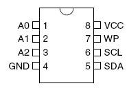
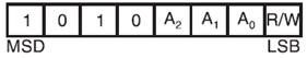
原理图上将A2、A1、A0都接地了,所以地址是0x50。
● AT24C02任意地址字节写的时序
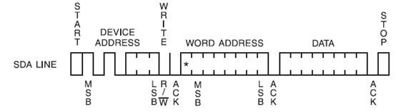
可见此时序符合前面提到的“单开始信号时序”
● AT24C02任意地址字节读的时序
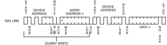
可见此时序符合前面提到的“多开始信号时序”
下面开始具体代码的分析(代码在2.6.22内核上测试通过):
/*i2c_test.c
* hongtao_liu <lht@farsight.com.cn>
*/
#include
#include
#include
#include
#include
#include
#include
#include
#define I2C_RETRIES 0x0701
#define I2C_TIMEOUT 0x0702
#define I2C_RDWR 0x0707
/*********定义struct i2c_rdwr_ioctl_data和struct i2c_msg,要和内核一致*******/
struct i2c_msg
{
unsigned short addr;
unsigned short flags;
#define I2C_M_TEN 0x0010
#define I2C_M_RD 0x0001
unsigned short len;
unsigned char *buf;
};
struct i2c_rdwr_ioctl_data
{
struct i2c_msg *msgs;
int nmsgs; /* nmsgs这个数量决定了有多少开始信号,对于“单开始时序”,取1*/
};
/***********主程序***********/
int main()
{
int fd,ret;
struct i2c_rdwr_ioctl_data e2prom_data;
fd=open("/dev/i2c-0",O_RDWR);
/*
*/dev/i2c-0是在注册i2c-dev.c后产生的,代表一个可操作的适配器。如果不使用i2c-dev.c
*的方式,就没有,也不需要这个节点。
*/
if(fd<0)
{
perror("openerror");
}
e2prom_data.nmsgs=2;
/*
*因为操作时序中,最多是用到2个开始信号(字节读操作中),所以此将
*e2prom_data.nmsgs配置为2
*/
e2prom_data.msgs=(struct i2c_msg*)malloc(e2prom_data.nmsgs*sizeof(struct i2c_msg));
if(!e2prom_data.msgs)
{
perror("mallocerror");
exit(1);
}
ioctl(fd,I2C_TIMEOUT,1);/*超时时间*/
ioctl(fd,I2C_RETRIES,2);/*重复次数*/
/***write data toe2prom**/
e2prom_data.nmsgs=1;
(e2prom_data.msgs[0]).len=2; //1个 e2prom 写入目标的地址和1个数据
(e2prom_data.msgs[0]).addr=0x50; //e2prom设备地址
(e2prom_data.msgs[0]).flags=0; //write
(e2prom_data.msgs[0]).buf=(unsignedchar*)malloc(2);
(e2prom_data.msgs[0]).buf[0]=0x10; //e2prom 写入目标的地址
(e2prom_data.msgs[0]).buf[1]=0x58; //thedata to write
ret=ioctl(fd,I2C_RDWR,(unsignedlong)&e2prom_data);
if(ret<0)
{
perror("ioctlerror1");
}
sleep(1);
/******read data frome2prom*******/
e2prom_data.nmsgs=2;
(e2prom_data.msgs[0]).len=1;//e2prom 目标数据的地址
(e2prom_data.msgs[0]).addr=0x50;// e2prom 设备地址
(e2prom_data.msgs[0]).flags=0;//write
(e2prom_data.msgs[0]).buf[0]=0x10;//e2prom数据地址
(e2prom_data.msgs[1]).len=1;//读出的数据
(e2prom_data.msgs[1]).addr=0x50;//e2prom 设备地址
(e2prom_data.msgs[1]).flags=I2C_M_RD;//read
(e2prom_data.msgs[1]).buf=(unsignedchar*)malloc(1);//存放返回值的地址。
(e2prom_data.msgs[1]).buf[0]=0;//初始化读缓冲
ret=ioctl(fd,I2C_RDWR,(unsignedlong)&e2prom_data);
if(ret<0)
{
perror("ioctlerror2");
}
printf("buff[0]=%x\n",(e2prom_data.msgs[1]).buf[0]);
/***打印读出的值,没错的话,就应该是前面写的0x58了***/
close(fd);
return 0;
}
以上讲述了一种比较常用的利用i2c-dev.c操作i2c设备的方法,这种方法可以说是在应用层完成了对具体i2c设备的驱动工作。
计划下一篇总结以下几点:
(1)在内核里写i2c设备驱动的两种方式:
● Probe方式(new style),如:
static struct i2c_driver pca953x_driver = {
.driver = {
.name ="pca953x",
},
.probe =pca953x_probe,
.remove =pca953x_remove,
.id_table =pca953x_id,
};
● Adapter方式(LEGACY),如:
static struct i2c_driver pcf8575_driver= {
.driver = {
.owner = THIS_MODULE,
.name ="pcf8575",
},
.attach_adapter =pcf8575_attach_adapter,
.detach_client =pcf8575_detach_client,
};
(2)适配器驱动编写方法
(3)分享一些项目中遇到的问题
四、在内核里写i2c设备驱动的两种方式
前文介绍了利用/dev/i2c-0在应用层完成对i2c设备的操作,但很多时候我们还是习惯为i2c设备在内核层编写驱动程序。目前内核支持两种编写i2c驱动程序的方式。下面分别介绍这两种方式的实现。这里分别称这两种方式为“Adapter方式(LEGACY)”和“Probe方式(new style)”。
(1)adapter方式(LEGACY)
(下面的实例代码是在2.6.27内核的pca953x.c基础上修改的,原始代码采用的是本文将要讨论的第2种方式,即Probe方式)
● 构建i2c_driver
static struct i2c_driver pca953x_driver = {
.driver = {
.name="pca953x", //名称
},
.id= ID_pca9555,//id号
.attach_adapter=pca953x_attach_adapter, //调用适配器连接设备
.detach_client=pca953x_detach_client,//让设备脱离适配器
};
● 注册i2c_driver
static int __init pca953x_init(void)
{
returni2c_add_driver(&pca953x_driver);
}
module_init(pca953x_init);
● attach_adapter动作
执行i2c_add_driver(&pca953x_driver)后会,如果内核中已经注册了i2c适配器,则顺序调用这些适配器来连接我们的i2c设备。此过程是通过调用i2c_driver中的attach_adapter方法完成的。具体实现形式如下:
static int pca953x_attach_adapter(struct i2c_adapter *adapter)
{
/*
adapter:适配器
addr_data:地址信息
pca953x_detect:探测到设备后调用的函数
*/
return i2c_probe(adapter, &addr_data, pca953x_detect);
}
地址信息addr_data是由下面代码指定的。
/* Addresses to scan*/
static unsigned short normal_i2c[] = {0x20,0x21,0x22,0x23,0x24,0x25,0x26,0x27,I2C_CLIENT_END};
I2C_CLIENT_INSMOD;
注意:normal_i2c里的地址必须是你i2c芯片的地址。否则将无法正确探测到设备。而I2C_CLIENT_INSMOD是一个宏,它会利用normal_i2c构建addr_data。
● 构建i2c_client,并注册字符设备驱动
i2c_probe在探测到目标设备后,后调用pca953x_detect,并把当时的探测地址address作为参数传入。
static int pca953x_detect(structi2c_adapter *adapter, int address, int kind)
{
struct i2c_client* new_client;
struct pca953x_chip* chip; //设备结构体
int err = 0,result;
dev_tpca953x_dev=MKDEV(pca953x_major,0);//构建设备号,根据具体情况设定,这里我只考虑了normal_i2c中只有一个地址匹配的情况。
if(!i2c_check_functionality(adapter, I2C_FUNC_SMBUS_BYTE_DATA|I2C_FUNC_SMBUS_WORD_DATA))//判定适配器能力
goto exit;
if (!(chip =kzalloc(sizeof(struct pca953x_chip), GFP_KERNEL))) {
err = -ENOMEM;
goto exit;
}
/****构建i2c-client****/
chip->client=kzalloc(sizeof(structi2c_client),GFP_KERNEL);
new_client =chip->client;
i2c_set_clientdata(new_client,chip);
new_client->addr =address;
new_client->adapter= adapter;
new_client->driver= &pca953x_driver;
new_client->flags =0;
strlcpy(new_client->name,"pca953x", I2C_NAME_SIZE);
if ((err =i2c_attach_client(new_client)))//注册i2c_client
goto exit_kfree;
if (err)
goto exit_detach;
if(pca953x_major)
{
result=register_chrdev_region(pca953x_dev,1,"pca953x");
}
else{
result=alloc_chrdev_region(&pca953x_dev,0,1,"pca953x");
pca953x_major=MAJOR(pca953x_dev);
}
if (result < 0) {
printk(KERN_NOTICE"Unable to get pca953x region, error%d\n", result);
return result;
}
pca953x_setup_cdev(chip,0);//注册字符设备,此处不详解
return 0;
exit_detach:
i2c_detach_client(new_client);
exit_kfree:
kfree(chip);
exit:
return err;
}
i2c_check_functionality用来判定设配器的能力,这一点非常重要。你也可以直接查看对应设配器的能力,如
static const struct i2c_algorithmsmbus_algorithm = {
.smbus_xfer=i801_access,
.functionality=i801_func,
};
static u32i801_func(struct i2c_adapter *adapter)
{
returnI2C_FUNC_SMBUS_QUICK | I2C_FUNC_SMBUS_BYTE |
I2C_FUNC_SMBUS_BYTE_DATA| I2C_FUNC_SMBUS_WORD_DATA |
I2C_FUNC_SMBUS_BLOCK_DATA| I2C_FUNC_SMBUS_WRITE_I2C_BLOCK
| (isich4 ?I2C_FUNC_SMBUS_HWPEC_CALC : 0);
}
● 字符驱动的具体实现
struct file_operation spca953x_fops = {
.owner = THIS_MODULE,
.ioctl= pca953x_ioctl,
.open=pca953x_open,
.release=pca953x_release,
};
字符设备驱动本身没有什么好说的,这里主要想说一下,如何在驱动中调用i2c设配器帮我们完成数据传输。
目前设配器主要支持两种传输方法:smbus_xfer和master_xfer。一般来说,如果设配器支持了master_xfer那么它也可以模拟支持smbus的传输。但如果只实现smbus_xfer,则不支持一些i2c的传输。
int(*master_xfer)(struct i2c_adapter *adap,struct i2c_msg *msgs,int num);
int (*smbus_xfer)(struct i2c_adapter *adap, u16 addr,
unsigned short flags,char read_write,
u8 command, int size,union i2c_smbus_data * data);
master_xfer中的参数设置,和前面的用户空间编程一致。现在只是要在驱动中构建相关的参数然后调用i2c_transfer来完成传输既可。
inti2c_transfer(struct i2c_adapter * adap, struct i2c_msg *msgs, int num)
smbus_xfer中的参数设置及调用方法如下:
static intpca953x_write_reg(struct pca953x_chip *chip, int reg, uint16_t val)
{
int ret;
ret = i2c_smbus_write_word_data(chip->client,reg << 1, val);
if (ret < 0) {
dev_err(&chip->client->dev,"failed writing register\n");
return -EIO;
}
return 0;
}
上面函数完成向芯片的地址为reg的寄存器写一个16bit的数据。i2c_smbus_write_word_data的实现如下:
s32 i2c_smbus_write_word_data(structi2c_client *client, u8 command, u16 value)
{
union i2c_smbus_datadata;
data.word = value;
returni2c_smbus_xfer(client->adapter,client->addr,client->flags,
I2C_SMBUS_WRITE,command,
I2C_SMBUS_WORD_DATA,&data);
}
从中可以看出smbus传输一个16位数据的方法。其它操作如:字符写、字符读、字读、块操作等,可以参考内核的i2c-core.c中提供的方法。
● 注销i2c_driver
static void __exit pca953x_exit(void)
{
i2c_del_driver(&pca953x_driver);
}
module_exit(pca953x_exit);
● detach_client动作
顺序调用内核中注册的适配器来断开我们注册过的i2c设备。此过程通过调用i2c_driver中的attach_adapter方法完成的。具体实现形式如下:
static int pca953x_detach_client(struct i2c_client *client)
{
int err;
struct pca953x_chip *data;
if ((err =i2c_detach_client(client)))//断开i2c_client
return err;
data=i2c_get_clientdata(client);
cdev_del(&(data->cdev));
unregister_chrdev_region(MKDEV(pca953x_major,0), 1);
kfree(data->client);
kfree(data);
return 0;
}
(2) Probe方式(new style)
● 构建i2c_driver
和LEGACY方式一样,也需要构建i2c_driver,但是内容有所不同。
static struct i2c_driver pca953x_driver = {
.driver = {
.name="pca953x",
},
.probe= pca953x_probe,//当有i2c_client和i2c_driver匹配时调用
.remove=pca953x_remove,//注销时调用
.id_table=pca953x_id,//匹配规则
};
● 注册i2c_driver
static int __init pca953x_init(void)
{
return i2c_add_driver(&pca953x_driver);
}
module_init(pca953x_init);
在注册i2c_driver的过程中,是将driver注册到了i2c_bus_type的总线上。此总线的匹配规则是:
static const struct i2c_device_id *i2c_match_id(const struct i2c_device_id *id, const structi2c_client *client)
{
while (id->name[0]){
if(strcmp(client->name, id->name) == 0)
return id;
id++;
}
return NULL;
}
可以看出是利用i2c_client的名称和id_table中的名称做匹配的。本驱动中的id_table为
static const struct i2c_device_id pca953x_id[] = {
{ "pca9534",8, },
{ "pca9535",16, },
{ "pca9536",4, },
{ "pca9537",4, },
{ "pca9538",8, },
{ "pca9539",16, },
{ "pca9554",8, },
{ "pca9555",16, },
{ "pca9557",8, },
{ "max7310",8, },
{ }
};
看到现在我们应该会有这样的疑问,在Adapter模式中,i2c_client是我们自己构造出来的,而现在的i2c_client是从哪来的呢?看看下面的解释
● 注册i2c_board_info
对于Probe模式,通常在平台代码中要完成i2c_board_info的注册。方法如下:
static struct i2c_board_info __initdata test_i2c_devices[] = {
{
I2C_BOARD_INFO("pca9555",0x27),//pca9555为芯片名称,0x27为芯片地址
.platform_data =&pca9555_data,
}, {
I2C_BOARD_INFO("mt9v022",0x48),
.platform_data =&iclink[0], /* With extender */
}, {
I2C_BOARD_INFO("mt9m001",0x5d),
.platform_data =&iclink[0], /* With extender */
},
};
i2c_register_board_info(0,test_i2c_devices,ARRAY_SIZE(test_i2c_devices)); //注册
i2c_client就是在注册过程中构建的。但有一点需要注意的是i2c_register_board_info并没有EXPORT_SYMBOL给模块使用。
● 字符驱动注册
在Probe方式下,添加字符驱动的位置在pca953x_probe中。
static int __devinit pca953x_probe(struct i2c_client *client,const struct i2c_device_id *id)
{
……
/****字符设备驱动注册位置****/
……
return 0;
}
● 注销i2c_driver
static void __exit pca953x_exit(void)
{
i2c_del_driver(&pca953x_driver);
}
module_exit(pca953x_exit);
● 注销字符设备驱动
在Probe方式下,注销字符驱动的位置在pca953x_remove中。
static int __devinit pca953x_remove (struct i2c_client *client)
{
……
/****字符设备驱动注销的位置****/
……
return 0;
}
● I2C设备的数据交互方法(即:调用适配器操作设备的方法)和Adapter方式下相同。
- 实例解析linux内核I2C体系结构
- 实例解析linux内核I2C体系结构
- 实例解析linux内核I2C体系结构
- 实例解析Linux内核I2C体系结构(1)
- 实例解析linux内核I2C体系结构
- 实例解析linux内核I2C体系结构
- 实例解析linux内核I2C体系结构
- 实例解析linux内核I2C体系结构
- 实例解析linux内核I2C体系结构
- 实例解析linux内核I2C体系结构
- 实例解析linux内核I2C体系结构
- 实例解析linux内核I2C体系结构
- 实例解析linux内核I2C体系结构
- 实例解析linux内核I2C体系结构
- 实例解析linux内核I2C体系结构
- 实例解析linux内核I2C体系结构
- 实例解析linux内核I2C体系结构 .
- 实例解析linux内核I2C体系结构 (2)
- 自己摸索简单EasySearch效果_winvay
- 有趣的rand()和srand()函数
- u-boot系统移植
- 游戏和学习两不相误
- 带横向滚动条的表格
- 实例解析linux内核I2C体系结构
- sql中in和exists的区别效率问题
- C++的继承
- 关于linux内核学习
- c#窗体间的传值_winvay
- dalivk tools
- 3D图像引擎,3D图像引擎原理
- [SQL Server]嵌套事务与分布式事务
- 按键实现arm开发板led灯