Network Virtualization: Beyond VLANs – Part 3: Switch Virtual Interfaces (SVIs)
来源:互联网 发布:ipadmini如何下载软件 编辑:程序博客网 时间:2024/06/11 09:33
- Part 1: VLANs
- Part 2: Subinterfaces
- Part 3: Switch Virtual Interfaces (SVIs)
- Part 4: Tunnels
- Part 5: Virtual Routing and Forwarding (VRF)
- Part 6: Overlay Networks
- Part 7: MPLS L3 VPNs
This can be accomplished by configuring the switch with a Switch Virtual Interfaces (SVI) on each of the VLANs. Conceptually you can think of it as running a virtual router inside the switch. This virtual router is automatically configured with a trunk connecting it to all VLANs and the SVIs function as its subinterfaces.
Using SVIs are pretty common nowadays and are usually used by L3 switches at the L2/L3 bounders of networks. Configuring an SVI is pretty simple:
Interface vlan 10 Ip address 10.10.10.1 255.255.255.0Interface vlan 20 Ip address 10.10.20.1 255.255.255.0I often see confusion when configuring only a VLAN on a switch vs. configuring both a VLAN and a SVI. I think this often stems from the nebulous boundary between Layer 2 and Layer 3 on a switch. Remember that a VLAN is purely in Layer 2, hosts on one VLAN (L2) cannot talk to host on other VLAN without a router (L3). So if you want the switch to act as the router for a VLAN then you configure an SVI for that VLAN. If you just want the switch to act like a traditional switch for that VLAN then you do not configure an SVI for that VLAN.
Whether the switch acts as a router for a VLAN is made on a VLAN by VLAN basis. A switch can have a SVI on some VLANs, acting as the router for those VLANs, and the same switch can have VLANs which it doesn’t have an SVI, where the switch does not act as a router for those VLAN. Usually a firewall or other non-router L3 devices are used to route packets to or from the VLANs without an SVI.
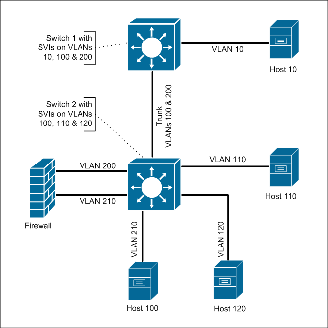
A situation where it’s common to see switches with SVIs on some VLANs but not others are in a DMZ switch deployment. Consider the following diagram.

In this design we have two switches; switch 1 has VLANs 10, 100 and 200 with a SVI on each and switch 2 with VLANs 100, 110, 120, 200 and 210 with SVIs on VLAN 100, 110 and 120 (switch 2 does not have a SVI on any of the VLANs in the 200 range). A firewall is connected to switch 2 with one interface in VLAN 200 and the other in VLAN 210.
In this design if host 110 wanted to talk to host 120, 110 would send a packet to the SVI on that VLAN and switch 2 would route the packet directly to VLAN 120. This is because switch 2 has SVIs on each of those VLANs and would have directly connected routes for these VLANs.
But what if host 110 wanted to talk to host 210? Again 110 would send a packet to switch 2’s SVI on VLAN 110, but switch 2 could not route the packet directly to VLAN 210. This is because even though VLAN 210 is configured on switch 2, it does not have an SVI for that VLAN. Switch 2 has an L2 connection to that VLAN, but not an L3 connection.
Instead switch 2 would have to route the packet on VLAN 100 via the trunk to switch 1. Switch 1 would then route the packet to VLAN 200 and send the packet to the firewall. The packet would be sent back over the trunk to switch 2, but switch 2 only acts as a normal run of the mill switch for that VLAN, so it only switches (L2) the packet (really the frame) to the port in VLAN 200 connected to the firewall.
The firewall received the packet, and then routes that packet out its interface connected to VLAN 210 on switch 2. Again switch 2 only just switches the packet on VLAN 210 to host 210.
So in this design the packet between host 110 and 210 pass through switch 2 several times, but in some cases switch 2 routes the packets and in other cases switch 2 only switches the packet.
I chose this design to make an example and it’s not the most efficient design. Can you think of any changes to the design to improve the efficiency while keeping host 210 firewalled from the rest of the network?
- Network Virtualization: Beyond VLANs – Part 3: Switch Virtual Interfaces (SVIs)
- Network Virtualization: Beyond VLANs – Part 1: VLANs
- Network Virtualization: Beyond VLANs – Part 5: Virtual Routing and Forwarding (VRF)
- Network Virtualization: Beyond VLANs – Part 2: Subinterfaces
- Network Virtualization: Beyond VLANs – Part 4: Tunnels
- Network Virtualization: Beyond VLANs – Part 6: Overlay Networks
- Network Virtualization: Beyond VLANs – Part 7: MPLS L3 VPNs
- Network Virtualization
- Network Virtualization
- Network Virtualization
- Implementing Angular2 forms – Beyond basics (part 3)
- VDS Best Practices – Virtual and Physical Switch Parameters (Part 2 of 6)
- What is Network Virtualization?
- Virtual Library Interfaces
- Virtualization for Network-based Multicore Telecommunication Systems – Current Status
- Introducing VMware NSX – The Platform For Network Virtualization
- APIC Virtualization and Virtual Interrupt
- virtualization--Create Virtual Machine#2
- 中国移动飞信免费发短信API接口(第三方 Fetion API)
- 字符串移位包含的问题
- Network Virtualization: Beyond VLANs – Part 2: Subinterfaces
- 如何显示数据库中Image类型的图片
- MCITP向导:SQL Server 2008 BI 开发人员
- Network Virtualization: Beyond VLANs – Part 3: Switch Virtual Interfaces (SVIs)
- Real-time operating systems (RTOS)
- 凯乐软件即将参展2012软博会并举办专题讲座,诚邀您的光临!
- Network Virtualization: Beyond VLANs – Part 4: Tunnels
- SVN客户端安装配置和使用(windows)
- C# EXCEL 导入导出类(OLEDB的方式)
- HDU 1515
- 介绍几个常用的jquery ui框架
- C# 操作EXCEL样式 示例 --生成EXCEL审计表


