Lighting with GLSL Phong Model
来源:互联网 发布:海岛奇兵人物升级数据 编辑:程序博客网 时间:2024/05/13 06:51
http://www.ozone3d.net/tutorials/glsl_lighting_phong.php

1 - Summary of the Phong Lighting Equation
2 - Point Light in GLSL
3 - Spot Light in GLSL
4 - Lighting Attenuation
5 - Further Resources
6 - Downloads
1 - Summary of the Phong Lighting Equation
The final color of the pixel displayed is given by the following equation:
If = Ia + Id + Is
where If is the intensity of the pixel final color, Ia is the intensity of the ambient color,Id is the intensity of the diffuse color and Is the intensity of the specular color.Ia, Id and Is are all four-dimensional RGBA vectors.
The Ia term is the ambient component. Ia is the result of the multiplication between the ambient component of the light and the ambient component of the material which composes the surface of the 3d object:
Ia = (Al * Am) + (As * Am)
where Al is the ambient component of the light and Am the ambient component of the material.Ia is generally a constant RGBA vector, and can even be pre-computed for the shader (this value is the same one independently from the pixel). A more advanced expression of this ambient term could be given by theAmbient Occlusion Lighting technique.
In OpenGL terms, As is defined as:
float As[4] = {0.1f, 0.1f, 0.1f, 1.0f };glLightModelfv( GL_LIGHT_MODEL_AMBIENT, As );With Demoniak3D, As is defined in the scene node:
<scene><global_ambient_light r="0.1" g="0.1" b="0.1" a="1.0" /></scene>
The Id term expresses the final diffuse component. This component is given by the following equation:
Id = Dl * Dm * LambertTerm
where Dl is the diffuse component of the light and Dm the diffuse component of the material. TheLambertTerm factor is the keystone of the lighting equations. It is actually the value of this factor which will make it possible to create the self shadow of a 3d object (self-shadowing). This Lambert coefficient is calculated with the following dot product:
LambertTerm = dot(N, L)
where N is the normal vector to the considered pixel and L the light vector at the same pixel. This simple relation but so fundamental, tells us that the value of the Lambert coefficient will be maximum (i.e. equals to 1.0) if the angle between the two vectors (L and N) equals zero, i.e. if the pixel is directly in front of the light. For all the other cases, the Lambert coefficient will vary between 0.0 and 1.0 what will generate the self shadow.
The Is term expresses the final specular component. This component is obtained by:
Is = Sm x Sl x pow( max(R dot E, 0.0), f )
The Is term is from far the most complicated to calculate but it is responsible of these famous specular reflexions on the surface of the objects.Sl is the specular component of the light and Sm the specular component of the material.E the view vector or camera vector and R is the reflected light vector.R is obtained with:
R = reflect(-L, N)
where N is the normal vector to the pixel considered, and L the light vector (the same than Lambert coefficient) and reflect() a function (available in GLSL) which makes it possible to calculate the reflexion vector of L in relation to N. One implementation of reflect() could be:
R = 2 * ( N dot L) * N - L
The pow() function is the power function which makes it possible to raise a number n to the power of p: pow(n, p).f is the specular exponential factor (the famous shininess in OpenGL) which represents the hardness and the precision of the specular reflexion.
At the OpenGL level, the light's ambient, diffuse and specular terms are defined by:
float Al[4] = {0.0f, 0.0f, 0.0f, 1.0f };glLightfv( GL_LIGHT0, GL_AMBIENT, Al );float Dl[4] = {1.0f, 1.0f, 1.0f, 1.0f };glLightfv( GL_LIGHT0, GL_DIFFUSE, Dl );float Sl[4] = {1.0f, 1.0f, 1.0f, 1.0f };glLightfv( GL_LIGHT0, GL_SPECULAR, Sl );And in Demoniak3D terms:
<light name="Light_01"><ambient r="0.0" g="0.0" b="0.0" a="1.0" /><diffuse r="1.0" g="1.0" b="1.0" a="1.0" /><specular r="1.0" g="1.0" b="1.0" a="1.0" /></light>
At the OpenGL level, the material's ambient, diffuse and specular terms are defined by:
float Am[4] = {0.3f, 0.3f, 0.3f, 1.0f };glMaterialfv(GL_FRONT_AND_BACK, GL_AMBIENT, Am );float Dm[4] = {0.9f, 0.5f, 0.5f, 1.0f };glMaterialfv(GL_FRONT_AND_BACK, GL_DIFFUSE, Dm );float Sm[4] = {0.6f, 0.6f, 0.6f, 1.0f };glMaterialfv(GL_FRONT_AND_BACK, GL_SPECULAR, Sm );float f = 60.0f;glMaterialf(GL_FRONT_AND_BACK, GL_SHININESS, f );And for Demoniak3D:
<material name="mat_torus" ><ambient r="0.3" g="0.3" b="0.3" a="1.0" /><diffuse r="0.9" g="0.5" b="0.5" a="1.0" /><specular r="0.6" g="0.6" b="0.6" a="1.0" exp="60.0" /></material>
2 - Point Light in GLSL![]()
In the rest of this article, we will use the Demoniak3D platform to integrate and test our GLSL vertex and pixel shaders. You should have a GLSL complient graphics controller. All nVidia Geforce FX 5200 and up and ATI Radeon 9500 and up support GLSL shaders. Of course, the latest version of graphics drivers should be installed too (Forceware for nVidia and Catalyst for ATI).
The above theory is valid for a point light (or omni-directional): its rays are cast in all directions. Since GLSL is a strongly vector-based language, the implementation of the above theory is quite direct.

Here is the code of the vertex shader:
[Vertex_Shader]varying vec3 normal, lightDir, eyeVec;void main(){normal = gl_NormalMatrix * gl_Normal;vec3 vVertex = vec3(gl_ModelViewMatrix * gl_Vertex);lightDir = vec3(gl_LightSource[0].position.xyz - vVertex);eyeVec = -vVertex;gl_Position = ftransform();}The main purpose of the vertex shader (beside gl_Position computing), is to provide all necessary vectors to the pixel shader (or fragment shader in OpenGL terminology). These vectors (normal, lightDir, eyeVec), once normalized in the pixel shader, will give us N, L and E vectors. One of the biggest problem with vector calculus is to know in which space we make calculus. At the vertex shader level, all calculus take place in the space of the camera. As a matter of fact, OpenGL gives us the position of the light (gl_LightSource[0].position.xyz) already in the space of the camera.
The varying keyword allows to create variables that will be passed to the pixel shader.
Here is the pixel shader code:
[Pixel_Shader]varying vec3 normal, lightDir, eyeVec;void main (void){vec4 final_color = (gl_FrontLightModelProduct.sceneColor * gl_FrontMaterial.ambient) + (gl_LightSource[0].ambient * gl_FrontMaterial.ambient);vec3 N = normalize(normal);vec3 L = normalize(lightDir);float lambertTerm = dot(N,L);if(lambertTerm > 0.0){final_color += gl_LightSource[0].diffuse * gl_FrontMaterial.diffuse * lambertTerm;vec3 E = normalize(eyeVec);vec3 R = reflect(-L, N);float specular = pow( max(dot(R, E), 0.0), gl_FrontMaterial.shininess );final_color += gl_LightSource[0].specular * gl_FrontMaterial.specular * specular;}gl_FragColor = final_color;}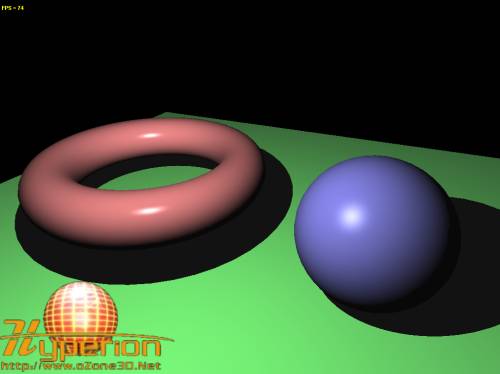
Fig.1 - The point_light.xml demo.
Here is a table that shows us equivalences between theorical terms seen above and GLSL implementation:
3 - Spot Light in GLSL![]()
Spot light radiates its rays in a cone. Shaders codes are the same as for point light but in the pixel shader there is a little change. We add a test in order to check whether or not the light ray direction is located in the cone. To perform this test, we're going to use two GLSL variables: gl_LightSource[0].spotDirection and gl_LightSource[0].spotCosCutoff.
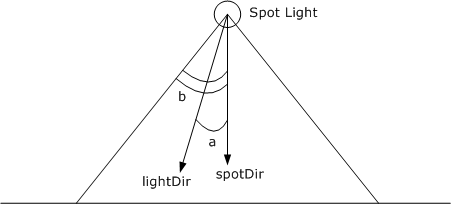
Fig.2 - Spot Light Configuration.
In order to know if the ray of light is located in cone of the light, we're going to compare the anglesa and b. If a is smaller than b then the ray is located in the cone. b is the spot cutoff angle (20 degrees in the demo).a is the angle between the direction of the spot and the current processing ray of light.
If lightDir and spotDir are normalized vectors, then to calculatea, we can do:
dot(lightDir, spotDir) = cos(a)
It would be nice to have the possibility to compare cos(a) directly without computing the inverse cosine. That's the role of the variablegl_LightSource[0].spotCosCutoff. It corresponds to the b angle cosine. Therefore, the test becomes:
if( dot(lightDir, spotDir) > gl_LightSource[0].spotCosCutoff ){// Do point light calculations.}We don't have to forget that the smaller the angle is, the greater the cosine is. That explains the way the test is done. Now, let's see the spot light pixel shader code:
[Pixel_Shader]varying vec3 normal, lightDir, eyeVec;void main (void){vec4 final_color = (gl_FrontLightModelProduct.sceneColor * gl_FrontMaterial.ambient) + (gl_LightSource[0].ambient * gl_FrontMaterial.ambient);vec3 L = normalize(lightDir);vec3 L = normalize(lightDir);vec3 D = normalize(gl_LightSource[0].spotDirection);if (dot(-L, D) > gl_LightSource[0].spotCosCutoff) {vec3 N = normalize(normal);float lambertTerm = max( dot(N,L), 0.0);if(lambertTerm > 0.0){final_color += gl_LightSource[0].diffuse * gl_FrontMaterial.diffuse * lambertTerm;vec3 E = normalize(eyeVec);vec3 R = reflect(-L, N);float specular = pow( max(dot(R, E), 0.0), gl_FrontMaterial.shininess );final_color += gl_LightSource[0].specular * gl_FrontMaterial.specular * specular;}}gl_FragColor = final_color;}The light vector is reversed because defined as the difference between the position of the spot light and the position of the current vertex in processing (see in the vertex shader code). So light and spot direction vectors are in opposition.
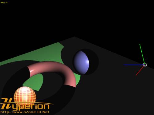
Fig.3 - spot_light.xml demo.
We dare say that the franc limit between the lighted area and the unlighted one is not really realistic. We are going to borrow Direct3D spot lights principle. D3D spots have two cones: the inner cone and the outer cone. The inner cone is equivalent to the OpenGL's one. The purpose is to get a decreasing intensity between the inner and the outer cones in order to create a area of penumbra. In that manner, the edge of the shadow will not be hard anymore but will be gradual and soft.
We're going to see a very simple method that consists in decreasing in a linear manner the light intensity using a variable calledfalloff. This variable is the ratio between the current angle between both cones and the difference between both cones. The shader code will help us to understand the technique:
[Pixel_Shader]varying vec3 normal, lightDir, eyeVec;const float cos_outer_cone_angle = 0.8; // 36 degreesvoid main (void){vec4 final_color = (gl_FrontLightModelProduct.sceneColor * gl_FrontMaterial.ambient) + (gl_LightSource[0].ambient * gl_FrontMaterial.ambient);vec3 L = normalize(lightDir);vec3 D = normalize(gl_LightSource[0].spotDirection);float cos_cur_angle = dot(-L, D);float cos_inner_cone_angle = gl_LightSource[0].spotCosCutoff;float cos_inner_minus_outer_angle = cos_inner_cone_angle - cos_outer_cone_angle;if (cos_cur_angle > cos_inner_cone_angle) {vec3 N = normalize(normal);float lambertTerm = max( dot(N,L), 0.0);if(lambertTerm > 0.0){final_color += gl_LightSource[0].diffuse * gl_FrontMaterial.diffuse * lambertTerm;vec3 E = normalize(eyeVec);vec3 R = reflect(-L, N);float specular = pow( max(dot(R, E), 0.0), gl_FrontMaterial.shininess );final_color += gl_LightSource[0].specular * gl_FrontMaterial.specular * specular;}}else if( cos_cur_angle > cos_outer_cone_angle ){float falloff = (cos_cur_angle - cos_outer_cone_angle) / cos_inner_minus_outer_angle;vec3 N = normalize(normal);float lambertTerm = max( dot(N,L), 0.0);if(lambertTerm > 0.0){final_color += gl_LightSource[0].diffuse * gl_FrontMaterial.diffuse * lambertTerm * falloff;vec3 E = normalize(eyeVec);vec3 R = reflect(-L, N);float specular = pow( max(dot(R, E), 0.0), gl_FrontMaterial.shininess );final_color += gl_LightSource[0].specular * gl_FrontMaterial.specular * specular * falloff;}}gl_FragColor = final_color;}Here is the result:
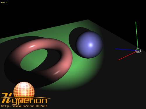
Fig.4 - The spot_light_enhanced_demo.xml demo.
Update: March 8, 2006:
Here is an optimized version of the previous pixel shader suggested by one of the forum members inthis topic This version removes one dynamic branching and seriously improves the code speed (there are about 100 FPS of difference between both pixel shaders!!!):
[Pixel_Shader]varying vec3 normal, lightDir, eyeVec;const float cos_outer_cone_angle = 0.8; // 36 degreesvoid main (void){vec4 final_color =(gl_FrontLightModelProduct.sceneColor * gl_FrontMaterial.ambient) +(gl_LightSource[0].ambient * gl_FrontMaterial.ambient);vec3 L = normalize(lightDir);vec3 D = normalize(gl_LightSource[0].spotDirection);float cos_cur_angle = dot(-L, D);float cos_inner_cone_angle = gl_LightSource[0].spotCosCutoff;float cos_inner_minus_outer_angle = cos_inner_cone_angle - cos_outer_cone_angle;//****************************************************// Don't need dynamic branching at all, precompute // falloff(i will call it spot)float spot = 0.0;spot = clamp((cos_cur_angle - cos_outer_cone_angle) / cos_inner_minus_outer_angle, 0.0, 1.0);//****************************************************vec3 N = normalize(normal);float lambertTerm = max( dot(N,L), 0.0);if(lambertTerm > 0.0){final_color += gl_LightSource[0].diffuse *gl_FrontMaterial.diffuse *lambertTerm * spot;vec3 E = normalize(eyeVec);vec3 R = reflect(-L, N);float specular = pow( max(dot(R, E), 0.0),gl_FrontMaterial.shininess );final_color += gl_LightSource[0].specular *gl_FrontMaterial.specular *specular * spot;}gl_FragColor = final_color;}4 - Lighting Attenuation![]()
Lighting equation coefficients that are dependent on a specific source of light can be optionally multiplied by an attenuation factor. This attenuation factor allows to simulate the light fading with distance.
If = (As*Am) + ((Al*Am) + Id + Is) * att
There are several ways to calculate the attenuation factor. We're going to see two of them.
4.1 - The standard method
This method exploits OpenGL coefficients of each light in GLSL:
- gl_LightSource[0].constantAttenuation or Kc
- gl_LightSource[0].linearAttenuation or Kl
- gl_LightSource[0].quadraticAttenuation or Kq
From these coefficients, the attenuation factor can be obtained by:
where d stands for the distance between the position of the light and the currenlty processed vertex:
lightDir = vec3(gl_LightSource[0].position.xyz - vVertex);float d = lenght(lightDir);
In OpenGL terms, attenuation factors are defined by:
glLightf( GL_LIGHT0, GL_CONSTANT_ATTENUATION, 0.0f );glLightf( GL_LIGHT0, GL_LINEAR_ATTENUATION , 0.0f );glLightf( GL_LIGHT0, GL_QUADRATIC_ATTENUATION , 0.0002 );
And in Demoniak3D, these factors are defined in the light node:
<light name="Light_01" constant_att="0.0" linear_att="0.0" quadratic_att="0.0002" />
Here is now our attenuated point light vertex shader:
[Vertex_Shader]varying vec3 normal, lightDir, eyeVec;varying float att;void main(){normal = gl_NormalMatrix * gl_Normal;vec3 vVertex = vec3(gl_ModelViewMatrix * gl_Vertex);lightDir = vec3(gl_LightSource[0].position.xyz - vVertex);eyeVec = -vVertex;float d = length(lightDir);att = 1.0 / ( gl_LightSource[0].constantAttenuation + (gl_LightSource[0].linearAttenuation*d) + (gl_LightSource[0].quadraticAttenuation*d*d) );gl_Position = ftransform();}And here is our attenuated point light pixel shader:
[Pixel_Shader]varying vec3 normal, lightDir, eyeVec;varying float att;void main (void){vec4 final_color = (gl_FrontLightModelProduct.sceneColor * gl_FrontMaterial.ambient) + (gl_LightSource[0].ambient * gl_FrontMaterial.ambient)*att;vec3 N = normalize(normal);vec3 L = normalize(lightDir);float lambertTerm = dot(N,L);if(lambertTerm > 0.0){final_color += gl_LightSource[0].diffuse * gl_FrontMaterial.diffuse * lambertTerm * att;vec3 E = normalize(eyeVec);vec3 R = reflect(-L, N);float specular = pow( max(dot(R, E), 0.0), gl_FrontMaterial.shininess );final_color += gl_LightSource[0].specular * gl_FrontMaterial.specular * specular * att;}gl_FragColor = final_color;}The attenuation factor is computed in the vertex shader and then is passed to the pixel shader through thevarying float att; variable.
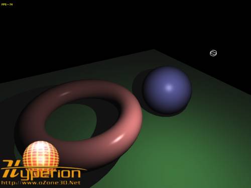
Fig.5 - The point_light_att.xml demo.
4.2 - Light Radius
This method uses an imaginary sphere in which the light lies in. This sphere represents the light's influence area (i.e the farthest distance an object can be influenced by the light). The attenuation factor decreases along the radius, and becomes equal to zero on the edge of and outside the sphere. This factor is calculated in the pixel shader and assumes that a variable holding the inverse of the radius of the sphere is defined (in order to avoid a division):
float distSqr = dot(lightDir, lightDir);float att = clamp(1.0 - invRadius * sqrt(distSqr), 0.0, 1.0);vec3 L = lightDir * inversesqrt(distSqr);
This piece of code needs to be explained. The norm of the lightDir vector, is given by:
This norm can be written using a dot product:
and
distSqr = dot(lightDir, lightDir)
distSqr and invRadius allow to calculate the attenuation factor. TheL vector, that is the normalized direction vector, can be obtenaid by the usual normalization formula:
magnitude: |r| = sqrt( distSqr )
unit vector u: u = (1/|r|) * U
unit vector u: u = inversesqrt(distSqr) * U
A value of invRadius=0.001 (i.e 1000.0 units radius) will allow you to start your tests.
The final word: all vertex / pixel shaders previously seen are for all-purposes (i.e they are not bound to Demoniak3D), do not take input parameters (i.e no uniform variables) and so they can be effortless used in any OpenGL application. That said, have a good coding!
5 - Further Resources
- Computer Graphics Using OpenGL: Chap: Introduction to Shading Models, p417 - ISBN: 0-02-354856-8.
- Implementing Lighting Models With HLSL: Theory and practice with Direct3D.
- The RenderMan Academy: Phong Shading Model: Theory and practice with RenderMan.
6 - Downloads
- Lighting with GLSL Phong Model
- Lighting with GLSL Phong Model
- Phong lighting model for diffuse reflection
- Lighting and environment mapping with GLSL
- OpenGL LIGHTING AND ENVIRONMENT MAPPING WITH GLSL
- GLSL(8)关于实现Phong shading model 中的一个小trick
- Blinn–Phong Shading Model
- GLSL实现简单硬件Anisotrop Lighting
- GLSL实现简单硬件Anisotrop Lighting
- OpenGL进阶(十三) - GLSL光照(Lighting)
- OpenGL进阶(十三) - GLSL光照(Lighting)
- Rendering with Vertex Lighting
- Using GLSL with SDL
- BUMPMAPPING WITH GLSL
- Unity shader 官网文档全方位学习(二)Lighting model及自定义Lighting model
- 现代OpenGL+Qt学习笔记之七:Phong光照及在GLSL中使用函数
- Advanced Lighting and Materials With Shaders
- Cg per-pixel lighting with vertex lights
- reinterpret_cast 和 static_cast
- 自绘实现半透明水晶按钮-一位大神的nx作品
- 视频播放的代码
- 如何使用BHO定制你的Internet Explorer浏览器
- Struts2/XWork 安全漏洞及解决办法
- Lighting with GLSL Phong Model
- soj 1702. Robot Roll Call -- Cambot...Servo...Gypsy...Croooow
- 音乐播放器的代码
- java的内隐类之匿名内部类的成员匿名内部类和方法匿名内部类
- 行车规则系统介绍
- [MFC]目录选择与文件选择
- POSIX线程:API
- 杭电1030 Delta-wave (找规律)
- C语言break和continue