Z-buffering
来源:互联网 发布:冒泡排序算法 编辑:程序博客网 时间:2024/04/30 09:43
In computer graphics, z-buffering, also known as depth buffering, is the management of image depth coordinates in three-dimensional (3-D) graphics, usually done in hardware, sometimes insoftware. It is one solution to thevisibility problem, which is the problem of deciding which elements of a rendered scene are visible, and which are hidden. Thepainter's algorithm is another common solution which, though less efficient, can also handle non-opaque scene elements.
When an object is rendered, the depth of a generated pixel (z coordinate) is stored in a buffer (the z-buffer or depth buffer). This buffer is usually arranged as a two-dimensional array (x-y) with one element for each screen pixel. If another object of the scene must be rendered in the same pixel, the method compares the two depths and overrides the current pixel if the object is closer to the observer. The chosen depth is then saved to the z-buffer, replacing the old one. In the end, the z-buffer will allow the method to correctly reproduce the usual depth perception: a close object hides a farther one. This is called z-culling.
The granularity of a z-buffer has a great influence on the scene quality: a 16-bit z-buffer can result in artifacts (called "z-fighting") when two objects are very close to each other. A24-bit or 32-bit z-buffer behaves much better, although the problem cannot be entirely eliminated without additional algorithms. An8-bit z-buffer is almost never used since it has too little precision.
Uses
Z-buffer data in the area of video editing permits one to combine 2D video elements in 3D space, permitting virtual sets, "ghostly passing through wall" effects, and complex effects like mapping of video on surfaces. An application forMaya, called IPR, permits one to perform post-rendering texturing on objects, utilizing multiple buffers like z-buffers, alpha, object id, UV coordinates and any data deemed as useful to the post-production process, saving time otherwise wasted in re-rendering of the video.
Z-buffer data obtained from rendering a surface from a light's POV permits the creation of shadows in a scanline renderer, by projecting the z-buffer data onto the ground and affected surfaces below the object. This is the same process used in non-raytracing modes by the free and open sourced 3D application Blender.
Developments
Even with small enough granularity, quality problems may arise when precision in the z-buffer's distance values is not spread evenly over distance. Nearer values are much more precise (and hence can display closer objects better) than values which are farther away. Generally, this is desirable, but sometimes it will cause artifacts to appear as objects become more distant. A variation on z-buffering which results in more evenly distributed precision is calledw-buffering (see below).
At the start of a new scene, the z-buffer must be cleared to a defined value, usually 1.0, because this value is the upper limit (on a scale of 0 to 1) of depth, meaning that no object is present at this point through theviewing frustum.
The invention of the z-buffer concept is most often attributed to Edwin Catmull, although Wolfgang Straßer also described this idea in his 1974 Ph.D. thesis1.
On recent PC graphics cards (1999–2005), z-buffer management uses a significant chunk of the availablememory bandwidth. Various methods have been employed to reduce the performance cost of z-buffering, such aslossless compression (computer resources to compress/decompress are cheaper than bandwidth) and ultra fast hardware z-clear that makes obsolete the "one frame positive, one frame negative" trick (skipping inter-frame clear altogether using signed numbers to cleverly check depths).
Z-culling
In rendering, z-culling is early pixel elimination based on depth, a method that provides an increase in performance when rendering of hidden surfaces is costly. It is a direct consequence of z-buffering, where the depth of each pixel candidate is compared to the depth of existing geometry behind which it might be hidden.
When using a z-buffer, a pixel can be culled (discarded) as soon as its depth is known, which makes it possible to skip the entire process of lighting andtexturing a pixel that would not bevisible anyway. Also, time-consuming pixel shaders will generally not be executed for the culled pixels. This makes z-culling a good optimization candidate in situations wherefillrate, lighting, texturing or pixel shaders are the mainbottlenecks.
While z-buffering allows the geometry to be unsorted, sorting polygons by increasing depth (thus using a reverse painter's algorithm) allows each screen pixel to be rendered fewer times. This can increase performance in fillrate-limited scenes with large amounts of overdraw, but if not combined with z-buffering it suffers from severe problems such as:
- polygons might occlude one another in a cycle (e.g. : triangle A occludes B, B occludes C, C occludes A), and
- there is no canonical "closest" point on a triangle (e.g.: no matter whether one sorts triangles by theircentroid or closest point or furthest point, one can always find two triangles A and B such that A is "closer" but in reality B should be drawn first).
As such, a reverse painter's algorithm cannot be used as an alternative to Z-culling (without strenuous re-engineering), except as an optimization to Z-culling. For example, an optimization might be to keep polygons sorted according to x/y-location and z-depth to provide bounds, in an effort to quickly determine if two polygons might possibly have an occlusion interaction.
Algorithm
Given: A list of polygons {P1,P2,.....Pn}
Output: A COLOR array, which displays the intensity of the visible polygon surfaces.
Initialize:
note : z-depth and z-buffer(x,y) is positive........ z-buffer(x,y)=max depth; and COLOR(x,y)=background color.
Begin:
for(each polygon P in the polygon list) do{ for(each pixel(x,y) that intersects P) do{ Calculate z-depth of P at (x,y) If (z-depth < z-buffer[x,y]) then{ z-buffer[x,y]=z-depth; COLOR(x,y)=Intensity of P at(x,y); } } } display COLOR array.Mathematics
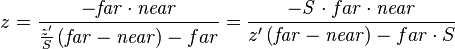
The range of depth values in camera space (see 3D projection) to be rendered is often defined between a  and
and value of
 . After aperspective transformation, the new value of , or
 , is defined by:

After an orthographic projection, the new value of , or, is defined by:

where is the old value of in camera space, and is sometimes called or
or .
.
The resulting values of are normalized between the values of -1 and 1, where theplane is at -1 and the plane is at 1. Values outside of this range correspond to points which are not in the viewingfrustum, and shouldn't be rendered.
Fixed-point representation
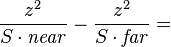
Typically, these values are stored in the z-buffer of the hardware graphics accelerator infixed point format. First they are normalized to a more common range which is [0,1] by substituting the appropriate conversion into the previous formula:

Second, the above formula is multiplied by  where d is the depth of the z-buffer (usually 16, 24 or 32 bits) and rounding the result to an integer:[1]

This formula can be inverted and derivated in order to calculate the z-buffer resolution (the 'granularity' mentioned earlier). The inverse of the above :
:
where
The z-buffer resolution in terms of camera space would be the incremental value resulted from the smallest change in the integer stored in the z-buffer, which is +1 or -1. Therefore this resolution can be calculated from the derivative of as a function of:
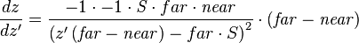
Expressing it back in camera space terms, by substituting by the above:


~ 
W-buffer
To implement a w-buffer,[clarification needed] the old values of in camera space, or, are stored in the buffer, generally infloating point format. However, these values cannot be linearly interpolated across screen space from the vertices—they usually have to beinverted[disambiguation needed], interpolated, and then inverted again. The resulting values of, as opposed to, are spaced evenly between and. There are implementations of the w-buffer that avoid the inversions altogether.
Whether a z-buffer or w-buffer results in a better image depends on the application.
See also
- Edwin Catmull
- 3D computer graphics
- Z-fighting
- Irregular Z-buffer
- Z-order
- Hierarchical Z-buffer
References
- ^The OpenGL Organization. "Open GL / FAQ 12 - The Depth buffer". http://www.opengl.org/resources/faq/technical/depthbuffer.htm. Retrieved 2010-11-01.
- ^Grégory Massal. "Depth buffer - the gritty details". http://www.codermind.com/articles/Depth-buffer-tutorial.html. Retrieved 2008-08-03.
External links
- Learning to Love your Z-buffer
- Alpha-blending and the Z-buffer
Notes
Note 1: see W.K. Giloi, J.L. Encarnação, W. Straßer. "The Giloi’s School of Computer Graphics". Computer Graphics 35 4:12–16.
- 3D computer graphics
- Z-buffering
- Shader 学习笔记 ---Z-Buffering or W-Buffering
- Double Buffering
- Triple Buffering
- 什么是double buffering和mutiple buffering
- 双缓冲 Double Buffering
- C#中的double buffering
- FPS, VSync, Triple Buffering
- python output buffering
- Double Buffering Windows Forms
- gstreamer network buffering mechanism
- Buffering and Caching
- buffering in standard streams
- Java IO - Buffering
- z
- z
- Z
- Z
- static_cast, dynamic_cast, reinterpret_cast, const_cast区别比较
- Struts2请求处理流程及源码分析
- C/C++面试题
- BlueStacks如何删除应用
- Hibernate继承映射与多态查询
- Z-buffering
- 基于cocos2d-x引擎的游戏框架设计
- PerferenceFragement 应用系列
- 自己写的WC程序, 参考了MINIx的command写法
- 黑马程序员 + 第19天 IO流
- 传感器-----测试手机支持那几种传感
- Ubuntu/linux下最强大的下载工具-aria2
- [zz]2002年你毕业了
- struct和union分析