S-Parameters
来源:互联网 发布:js 获取map 的键和值 编辑:程序博客网 时间:2024/05/09 08:49
http://www.antenna-theory.com/definitions/sparameters.php
S-parameters describe the input-output relationship between ports (or terminals) in an electricalsystem. For instance, if we have 2 ports (intelligently called Port 1 and Port 2), thenS12 represents the power transferred from Port 2 to Port 1. S21 represents the power transferredfrom Port 1 to Port 2. In general, SNM represents the power transferred from Port M to Port Nin a multi-port network.
A port can be loosely defined as any place where we can deliver voltage and current. So, if we havea communication system with two radios (radio 1 and radio 2), then the radio terminals (which deliver power to the two antennas)would be the two ports. S11 then would be the reflected power radio 1 is trying to deliver to antenna 1. S22 would be the reflectedpower radio 2 is attempting to deliver to antenna 2. And S12 is the power from radio 2 that is delivered through antenna 1 to radio 1.Note that in general S-parameters are a function of frequency (i.e. vary with frequency).
As an example, consider the following two-port network:
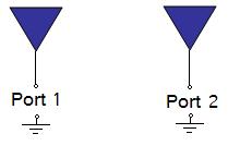
In the above Figure, S21 represents the power received at antenna 2 relative to the power input toantenna 1. For instance, S21=0 dB implies that all the power delivered to antenna 1 ends upat the terminals of antenna 2. If S21=-10 dB, then if1 Watt (or 0 dB) is delivered to antenna 1, then -10 dB (0.1 Watts) of power is received at antenna 2.
If an amplifier exists in the circuitry, then S21 can show gain (i.e. S21 > 0 dB). This means that for 1 W ofpower delivered to Port 1, more than 1 W of power is received at Port 2.
In practice, the most commonly quoted parameter in regards to antennas is S11. S11 representshow much power is reflected from the antenna, and hence is known as thereflection coefficient (sometimes writtenas gamma:  orreturn loss.If S11=0 dB, then all the power is reflectedfrom the antenna and nothing is radiated. If S11=-10 dB, this implies that if 3 dB of power is deliveredto the antenna, -7 dB is the reflected power. The remainder of the power was "accepted by" or deliverd to the antenna. Thisaccepted power is either radiated or absorbed as losses within the antenna. Since antennasare typically designed to be low loss, ideally the majority of the power delivered to the antennais radiated. See alsoVSWR, which is directly related to S11.
As an example, consider the plot of S11 in the following figure:
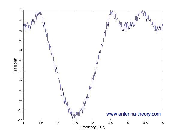
The above would typically be measured using aVector Network Analyzer (VNA),which can plot S11. Theabove figure implies that the antenna radiates best at 2.5 GHz, where S11=-10 dB. Further, at1.5 GHz the antenna will radiate virtually nothing, as S11 is close to 0 dB (so all the power is reflected).Theantenna bandwidthcan also be determined from the above figure. If the bandwidth is defined as the frequency range where S11 is to be less than -6 dB,thenthe bandwidth would be roughly 1 GHz, with 3 GHz the high end and 2 GHz the low end of the frequencyband.
- S-Parameters
- Parameters
- Parameters
- Parameters
- parameters
- ls, find and grep's parameters and xargs
- Joomla! (DAY 6) - Joomsport (DAY 4): Tackling with View's Parameters - JElement
- 【QQ互联】【解决】client request's parameters are invalid, invalid openid
- QQ connect client request's parameters are invalid, invalid openid 问题的解决
- struts2 #parameters.XXX获取参数 在s:if标签中判断要注意!
- Avoid passing null as the view root (needed to resolve layout parameters on the inflated layout's ro
- Avoid passing null as the view root (needed to resolve layout parameters on the inflated layout's r
- Parameters.. sittings
- JVM Parameters
- Database Parameters
- Parameters用法
- Parameters用法
- 13、Parameters
- Linux上配置java环境、android的SDK环境
- 如何让SqlParameter的值为null 传入SQL
- T-SQL with关键字 with as 递归循环表
- 关于反射的具体使用
- opencv haartraining 分析二:每级stage正负样本的获取
- S-Parameters
- tabbar背景颜色设置成自己的图片
- LeetCode Merge Two Sorted Lists
- 软件工程视频总结(1)--思想提升
- ARM汇编特殊符号 汇编符号引用
- 输入阻抗 输出阻抗
- 关于webservice的使用
- 阻抗匹配基础
- 初识IOC