OER Voice Traffic Optimization Using Active Probes
来源:互联网 发布:表格软件扫描录入 编辑:程序博客网 时间:2024/06/11 17:45
Table Of Contents
OER Voice Traffic Optimization Using Active Probes
Finding Feature Information
Contents
Prerequisites for OER Voice Traffic Optimization Using Active Probes
Information About OER Voice Traffic Optimization Using Active Probes
Voice Quality on IP Networks
Probes Used by OER
OER Voice Traffic Optimization Using Active Probes
How to Configure OER Voice Traffic Optimization Using Active Probes
Identifying Traffic for OER Using a Prefix List
Identifying Voice Traffic to Optimize Using an Access List
IP Protocol Stack for Voice
Configuring OER Voice Probes with a Target Assignment
Examples
What to do Next
Configuration Examples for OER Voice Traffic Optimization Using Active Probes
Optimizing Only Voice Traffic Using Active Probes: Example
Optimizing Traffic (Including Voice Traffic) Using Active Probes: Example
Where to Go Next
Additional References
Related Documents
Technical Assistance
Feature Information for OER Voice Traffic Optimization Using Active Probes
OER Voice Traffic Optimization Using Active Probes
This module documents an Optimized Edge Routing (OER) solution that supports outbound optimization of voice traffic based on the voice metrics, jitter and Mean Opinion Score (MOS). Jitter and MOS are important quantitative quality metrics for voice traffic and these voice metrics are measured using Optimized Edge Routing (OER) active probes.
OER provides automatic route optimization and load distribution for multiple connections between networks. OER is an integrated Cisco IOS solution that allows you to monitor IP traffic flows and then define policies and rules based on prefix performance, link load distribution, link bandwidth monetary cost, and traffic type. OER provides active and passive monitoring systems, dynamic failure detection, and automatic path correction. Deploying OER enables intelligent load distribution and optimal route selection in an enterprise network.
Finding Feature Information
Your software release may not support all the features documented in this module. For the latest feature information and caveats, see the release notes for your platform and software release. To find information about the features documented in this module, and to see a list of the releases in which each feature is supported, see the "Feature Information for OER Voice Traffic Optimization Using Active Probes" section.
Use Cisco Feature Navigator to find information about platform support and Cisco IOS and Catalyst OS software image support. To access Cisco Feature Navigator, go to http://www.cisco.com/go/cfn. An account on Cisco.com is not required.
Contents
•![]() Prerequisites for OER Voice Traffic Optimization Using Active Probes
Prerequisites for OER Voice Traffic Optimization Using Active Probes
•![]() Information About OER Voice Traffic Optimization Using Active Probes
Information About OER Voice Traffic Optimization Using Active Probes
•![]() How to Configure OER Voice Traffic Optimization Using Active Probes
How to Configure OER Voice Traffic Optimization Using Active Probes
•![]() Configuration Examples for OER Voice Traffic Optimization Using Active Probes
Configuration Examples for OER Voice Traffic Optimization Using Active Probes
•![]() Where to Go Next
Where to Go Next
•![]() Additional References
Additional References
•![]() Feature Information for OER Voice Traffic Optimization Using Active Probes
Feature Information for OER Voice Traffic Optimization Using Active Probes
Prerequisites for OER Voice Traffic Optimization Using Active Probes
Before implementing OER optimization for voice traffic, you need to understand an overview of how OER works and how to set up OER network components. See the "Cisco IOS Optimized Edge Routing Overview" and"Setting Up OER Network Components" modules for more details. For a list of other OER configuration modules, see the "Where to Go Next" section and the "Related Documents" section.
Information About OER Voice Traffic Optimization Using Active Probes
Before you configure OER voice traffic optimization, you should understand the following concepts:
•![]() Voice Quality on IP Networks
Voice Quality on IP Networks
•![]() Probes Used by OER
Probes Used by OER
•![]() OER Voice Traffic Optimization Using Active Probes
OER Voice Traffic Optimization Using Active Probes
Voice Quality on IP Networks
Voice packets traveling through an IP network are no different from data packets. In the plain old telephone system (POTS), voice traffic travels over circuit-switched networks with predetermined paths and each phone call is given a dedicated connection for the duration of the call. Voice traffic using POTS has no resource contention issues, but voice traffic over an IP network has to contend with factors such as delay, jitter, and packet loss, which can affect the quality of the phone call.
Delay
Delay (also referred as latency) for voice packets is defined as the delay between when the packet was sent from the source device and when it arrived at a destination device. Delay can be measured as one-way delay or round-trip delay. The largest contributor to latency is caused by network transmission delay. Round-trip delay affects the dynamics of conversation and is used in Mean Opinion Score (MOS) calculations. One-way delay is used for diagnosing network problems. A caller may notice a delay of 200 milliseconds and try to speak just as the other person is replying because of packet delay. The telephone industry standard specified in ITU-T G.114 recommends the maximum desired one-way delay be no more than 150 milliseconds. Beyond a one-way delay of 150 milliseconds, voice quality is affected. With a round-trip delay of 300 milliseconds or more, users may experience annoying talk-over effects.
Jitter
Jitter means interpacket delay variance. When multiple packets are sent consecutively from source to destination, for example, 10 ms apart, and if the network is behaving ideally, the destination should be receiving them 10 ms apart. But if there are delays in the network (like queuing, arriving through alternate routes, and so on) the arrival delay between packets might be greater than or less than 10 ms. Using this example, a positive jitter value indicates that the packets arrived more than 10 ms apart. If the packets arrive 12 ms apart, then positive jitter is 2 ms; if the packets arrive 8 ms apart, then negative jitter is 2 ms. For delay-sensitive networks like VoIP, positive jitter values are undesirable, and a jitter value of 0 is ideal.
Packet Loss
Packet loss can occur due an interface failing, a packet being routed to the wrong destination, or congestion in the network. Packet loss for voice traffic leads to the degradation of service in which a caller hears the voice sound with breaks. Although average packet loss is low, voice quality may be affected by a short series of lost packets.
Mean Opinion Score (MOS)
With all the factors affecting voice quality, many people ask how voice quality can be measured. Standards bodies like the ITU have derived two important recommendations: P.800 (MOS) and P.861 (Perceptual Speech Quality Measurement [PSQM]). P.800 is concerned with defining a method to derive a Mean Opinion Score of voice quality. MOS scores range between 1 representing the worst voice quality, and 5 representing the best voice quality. A MOS of 4 is considered "toll-quality" voice.
Probes Used by OER
OER uses some of the IP SLA probes to help gather the data OER requires to make its decisions.
Cisco IOS IP SLAs
Cisco IOS IP SLAs are an embedded feature set in Cisco IOS software and they allow you to analyze IP service levels for IP applications and services, to increase productivity, to lower operational costs, and to reduce occurrences of network congestion or outages. IP SLAs use active traffic monitoring—the generation of traffic in a continuous, reliable, and predictable manner—for measuring network performance. The accuracy of measured data is enhanced by enabling the IP SLAs Responder, available in Cisco routers, on the destination device. For more details about IP SLAs, see the Cisco IOS IP SLAs Configuration Guide.
Active Probe Types Used by OER
The following types of active probes can be configured:
ICMP Echo—A ping is sent to the target address. OER uses ICMP Echo probes, by default, when an active probe is automatically generated. Configuring an ICMP echo probe does not require knowledgeable cooperation from the target device. However, repeated probing could trigger an Intrusion Detection System (IDS) alarm in the target network. If an IDS is configured in a target network that is not under your control, we recommend that you notify the administrator of this target network.
Jitter—A jitter probe is sent to the target address. A target port number must be specified. A remote responder must be enabled on the target device, regardless of the configured port number.
TCP Connection—A TCP connection probe is sent to the target address. A target port number must be specified. A remote responder must be enabled if TCP messages are configured to use a port number other than TCP port number 23, which is well-known.
UDP Echo—A UDP echo probe is sent to the target address. A target port number must be specified. A remote responder must be enabled on the target device, regardless of which port number is configured.
Probe Frequency
In Cisco IOS Release 12.4(4)T and earlier releases, the frequency of an active probe used by OER was set to 60 seconds. In Cisco IOS Release 12.4(6)T and 12.2(33)SRB, the frequency can be increased for each policy by configuring a lower time-interval between two probes. Increased probe frequency can reduce the response time and provide a better approximation of the MOS-low count percentage
OER Voice Traffic Optimization Using Active Probes
OER voice traffic optimization provides support for outbound optimization of voice traffic on the basis of the voice performance metrics, delay, packet loss, jitter, and MOS. Delay, packet loss, jitter and MOS are important quantitative quality metrics for voice traffic, and these voice metrics are measured using OER active probes. In Cisco IOS Release 12.4(4)T and earlier releases, OER probes could measure delay and packet loss, but not jitter and MOS. The IP SLA jitter probe is integrated with OER to measure jitter (source to destination) and the MOS score in addition to measuring delay and packet loss. The jitter probe requires a responder on the remote side just like the UDP Echo probe. Integration of the IP SLA jitter probe type in OER enhances the ability of OER to optimize voice traffic. OER policies can be configured to set the threshold and priority values for the voice performance metrics: delay, packet loss, jitter, and MOS.
Configuring an OER policy to measure jitter involves configuring only the threshold value and not relative changes (used by other OER features) because for voice traffic, relative jitter changes have no meaning. For example, jitter changes from 5 milliseconds to 25 milliseconds are just as bad in terms of voice quality as jitter changes from 15 milliseconds to 25 milliseconds. If the short-term average (measuring the last 5 minutes) jitter is higher than the jitter threshold, the prefix is considered out-of-policy due to jitter. OER then probes all exits, and the exit with the least jitter is selected as the best exit.
MOS policy works in a different way. There is no meaning to average MOS values, but there is meaning to the number of times that the MOS value is below the MOS threshold. For example, if the MOS threshold is set to 3.85 and if 3 out of 10 MOS measurements are below the 3.85 MOS threshold, the MOS-low-count is 30 percent. When OER runs a policy configured to measure MOS, both the MOS threshold value and the MOS-low-count percentage are considered. A prefix is considered out-of-policy if the short term (during the last 5 minutes) MOS-low-count percentage is greater than the configured value for a given MOS threshold. OER then probes all exits, and the exit with the highest MOS value is selected as the best exit.
OER Forced Target Assignment
In Cisco IOS Release 12.4(4)T and earlier releases, the OER active probe target is assigned to the longest matched prefix. There are some scenarios where you may want to use a target that does not match the destination prefix. The example in Figure 1 explains a scenario in which configuring an OER forced target assignment is more appropriate than using the longest match prefix.
Figure 1 OER Forced Target Assignment Scenario
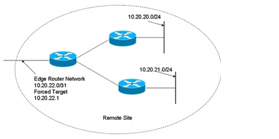
In Figure 1 we want to probe IP address 10.20.22.1 (at the edge of the network) for either network 10.20.21.0/24 or 10.20.22.0/24. Jitter is less likely to be introduced within the network so probing the edge of the network gives a measurement that is close to probing the final destination.
Forced target assignment allows you to assign a target to a group of prefixes or an application, even if they are not the longest match prefixes. Assigning a target can determine the true delay to the edge of a network rather than delay to an end host.
How to Configure OER Voice Traffic Optimization Using Active Probes
Configuring OER to optimize voice traffic using active probes involves several decisions and subsequent branching tasks. The first step is to identify the traffic to be optimized and decide whether to use a prefix list or an access list. Use a prefix list to identify all traffic, including voice traffic, with a specific set of destination prefixes. Use an access list to identify only voice traffic with a specific destination prefix and carried over a specific protocol.
The second step in optimizing voice traffic is to configure active probing using the active-probe or set active-probe command to specify the type of active probe to be used. In Cisco IOS Release 12.4(6)T and 12.2(33)SRB, the ability to set a forced target assignment for the active probe was introduced.
The final step in optimizing voice traffic is to configure an OER policy to set the performance metrics that you want OER to apply to the identified traffic.
Perform one of the first two optional tasks, depending on whether you want to use a prefix list or an access list to identify the traffic to be optimized. The third task can be used with traffic identified using an access list, and it also demonstrates how to use a forced target assignment. For an example configuration that can be used with traffic identified using a prefix list, see the "Optimizing Traffic (Including Voice Traffic) Using Active Probes: Example" section.
•![]() Identifying Traffic for OER Using a Prefix List
Identifying Traffic for OER Using a Prefix List
•![]() Identifying Voice Traffic to Optimize Using an Access List
Identifying Voice Traffic to Optimize Using an Access List
•![]() Configuring OER Voice Probes with a Target Assignment
Configuring OER Voice Probes with a Target Assignment
Identifying Traffic for OER Using a Prefix List
Before traffic can be measured using OER, it must be identified. Perform this task to use a prefix list to identify the traffic that OER will probe.
SUMMARY STEPS
1.![]() enable
enable
2.![]() configure terminal
configure terminal
3.![]() ip prefix-list list-name [seq seq-value] {deny network/length | permit network/length} [ge ge-value] [le le-value]
ip prefix-list list-name [seq seq-value] {deny network/length | permit network/length} [ge ge-value] [le le-value]
4.![]() exit
exit
DETAILED STEPS
Step 1
enable
Router> enable
Enables privileged EXEC mode.
•![]() Enter your password if prompted.
Enter your password if prompted.
Step 2
configure terminal
Router# configure terminal
Enters global configuration mode.
Step 3
ip prefix-list list-name [seq seq-value] {deny network/length |permit network/length} [ge ge-value] [le le-value]
Router(config)# ip prefix-list TRAFFIC_PFX_LIST seq 10 permit 10.20.21.0/24
Creates an IP prefix list.
•![]() IP prefix lists are used to manually select prefixes for monitoring by the OER master controller.
IP prefix lists are used to manually select prefixes for monitoring by the OER master controller.
•![]() A master controller can monitor and control an exact prefix (/32), a specific prefix length, or a specific prefix length and any prefix that falls under the prefix length (for example, a /24 under a /16).
A master controller can monitor and control an exact prefix (/32), a specific prefix length, or a specific prefix length and any prefix that falls under the prefix length (for example, a /24 under a /16).
•![]() A prefix range can also be selected using the le keyword with a 32-bit prefix length.
A prefix range can also be selected using the le keyword with a 32-bit prefix length.
•![]() The prefixes specified in the IP prefix list are imported into an OER map using the match ip address(OER) command.
The prefixes specified in the IP prefix list are imported into an OER map using the match ip address(OER) command.
•![]() The example creates an IP prefix list named TRAFFIC_PFX_LIST that permits prefixes from the 10.20.21.0/24 subnet.
The example creates an IP prefix list named TRAFFIC_PFX_LIST that permits prefixes from the 10.20.21.0/24 subnet.
Step 4
exit
Router(config)# exit
(Optional) Exits global configuration mode and returns to privileged EXEC mode.
Identifying Voice Traffic to Optimize Using an Access List
Before voice traffic can be measured, it must be identified. Perform this task to use an access list to identify the voice traffic.
IP Protocol Stack for Voice
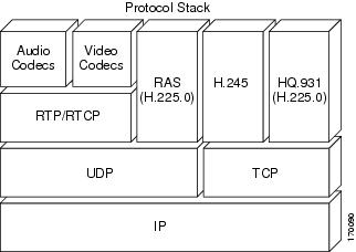
Voice traffic uses a variety of protocols and streams on the underlying IP network. Figure 2 is a representation of the protocol options available for carrying voice traffic over IP. Most signaling traffic for voice is carried over TCP. Most voice calls are carried over User Datagram Protocol (UDP) and Real-Time Protocol (RTP). You can configure your voice devices to use a specific range of destination port numbers over UDP to carry voice call traffic.
Figure 2 Protocol Stack Options Available for Voice Traffic
SUMMARY STEPS
1.![]() enable
enable
2.![]() configure terminal
configure terminal
3.![]() ip access list {standard | extended} access-list-name
ip access list {standard | extended} access-list-name
4.![]() [sequence-number] permit udp source source-wildcard [operator [port]] destination destination-wildcard[operator [port]] [precedence precedence] [tos tos] [ttl operator value] [log] [time-range time-range-name] [fragments]
[sequence-number] permit udp source source-wildcard [operator [port]] destination destination-wildcard[operator [port]] [precedence precedence] [tos tos] [ttl operator value] [log] [time-range time-range-name] [fragments]
5.![]() exit
exit
DETAILED STEPS
Step 1
enable
Router> enable
Enables privileged EXEC mode.
•![]() Enter your password if prompted.
Enter your password if prompted.
Step 2
configure terminal
Router# configure terminal
Enters global configuration mode.
Step 3
ip access-list {standard |extended} access-list-name
Router(config)# ip access-list extended VOICE_ACCESS_LIST
Defines an IP access list by name.
•![]() OER supports only named access lists.
OER supports only named access lists.
•![]() The example creates an extended IP access list named VOICE_ACCESS_LIST.
The example creates an extended IP access list named VOICE_ACCESS_LIST.
Step 4
[sequence-number] permit udpsource source-wildcard[operator [port]] destination destination-wildcard [operator[port]] [precedenceprecedence] [tos tos] [ttloperator value] [log] [time-range time-range-name] [fragments]
Router(config-ext-nacl)# permit udp any range 16384 32767 10.20.20.0 0.0.0.15 range 16384 32767
Defines the extended access list.
•![]() Any protocol, port, or other IP packet header value can be specified.
Any protocol, port, or other IP packet header value can be specified.
•![]() The example is configured to identify all UDP traffic ranging from a destination port number of 16384 to 32767 from any source to a destination prefix of 10.20.20.0/24. This specific UDP traffic is to be optimized.
The example is configured to identify all UDP traffic ranging from a destination port number of 16384 to 32767 from any source to a destination prefix of 10.20.20.0/24. This specific UDP traffic is to be optimized.
Step 5
exit
Router(config)# exit
(Optional) Exits global configuration mode and returns to privileged EXEC mode.
Configuring OER Voice Probes with a Target Assignment
After identifying the traffic (in this example, voice traffic identified using an access list) to be optimized, perform this task to configure the OER jitter probes and assign the results of the jitter probes to optimize the identified traffic. In this task, the OER active voice probes are assigned a forced target for OER instead of the usual longest match assigned target. Before configuring the OER jitter probe on the source device, the IP SLAs Responder must be enabled on the target device (the operational target). The IP SLAs Responder is available only on Cisco IOS software-based devices. Start this task at the network device that runs the IP SLAs Responder.

Note![]() The device that runs the IP SLAs Responder does not have to be configured for OER.
The device that runs the IP SLAs Responder does not have to be configured for OER.
Note![]() Policies applied in an OER map do not override global policy configurations.
Policies applied in an OER map do not override global policy configurations.
Prerequisites
Before configuring this task, perform the "Identifying Voice Traffic to Optimize Using an Access List" section.
SUMMARY STEPS
1.![]() enable
enable
2.![]() configure terminal
configure terminal
3.![]() ip sla monitor responder
ip sla monitor responder
4.![]() exit
exit
5.![]() Move to the network device that is the OER master controller.
Move to the network device that is the OER master controller.
6.![]() enable
enable
7.![]() configure terminal
configure terminal
8.![]() oer-map map-name sequence-number
oer-map map-name sequence-number
9.![]() match ip address {access-list access-list-name | prefix-list prefix-list-name}
match ip address {access-list access-list-name | prefix-list prefix-list-name}
10.![]() set active probe probe-type ip-address [target-port number] [codec codec-name]
set active probe probe-type ip-address [target-port number] [codec codec-name]
11.![]() set probe frequency seconds
set probe frequency seconds
12.![]() set jitter threshold maximum
set jitter threshold maximum
13.![]() set mos threshold minimum percent percent
set mos threshold minimum percent percent
14.![]() set resolve {cost priority value | delay priority value variance percentage | jitter priority value variancepercentage | loss priority value variance percentage | mos priority value variance percentage | range priority value | utilization priority value variance percentage}
set resolve {cost priority value | delay priority value variance percentage | jitter priority value variancepercentage | loss priority value variance percentage | mos priority value variance percentage | range priority value | utilization priority value variance percentage}
15.![]() set resolve mos priority value variance percentage
set resolve mos priority value variance percentage
16.![]() set delay {relative percentage | threshold maximum}
set delay {relative percentage | threshold maximum}
17.![]() exit
exit
18.![]() oer master
oer master
19.![]() policy-rules map-name
policy-rules map-name
20.![]() end
end
21.![]() show oer master active-probes forced
show oer master active-probes forced
22.![]() show oer master policy {sequence-number | policy-name | default}
show oer master policy {sequence-number | policy-name | default}
DETAILED STEPS
Step 1
enable
Router> enable
Enables privileged EXEC mode.
•![]() Enter your password if prompted.
Enter your password if prompted.
Step 2
configure terminal
Router# configure terminal
Enters global configuration mode.
Step 3
ip sla monitor responder
Router(config)# ip sla monitor responder
Enables the IP SLAs Responder.
Step 4
exit
Router(config)# exit
Exits global configuration mode and returns to privileged EXEC mode.
Step 5
Move to the network device that is the OER master controller.
—
Step 6
enable
Router> enable
Enables privileged EXEC mode.
•![]() Enter your password if prompted.
Enter your password if prompted.
Step 7
configure terminal
Router# configure terminal
Enters global configuration mode.
Step 8
oer-map map-name sequence-number
Router(config)# oer-map TARGET_MAP 10
Enters OER map configuration mode to configure an OER map to apply policies to selected IP prefixes.
•![]() Only one match clause can be configured for each OER map sequence.
Only one match clause can be configured for each OER map sequence.
•![]() Deny sequences are first defined in an IP prefix list and then applied with thematch ip address (OER) command in Step 9.
Deny sequences are first defined in an IP prefix list and then applied with thematch ip address (OER) command in Step 9.
•![]() The example creates an OER map named TARGET_MAP.
The example creates an OER map named TARGET_MAP.
Step 9
match ip address {access-list access-list-name |prefix-list prefix-list-name}
Router(config-oer-map)# match ip address access-list VOICE_ACCESS_LIST
References an extended IP access list or IP prefix as match criteria in an OER map.
•![]() Only a single match clause can be configured for each OER map sequence.
Only a single match clause can be configured for each OER map sequence.
•![]() The example configures the IP access list named VOICE_ACCESS_LIST as match criteria in an OER map. The access list was created in the "Identifying Voice Traffic to Optimize Using an Access List" task.
The example configures the IP access list named VOICE_ACCESS_LIST as match criteria in an OER map. The access list was created in the "Identifying Voice Traffic to Optimize Using an Access List" task.
Step 10
set active-probe probe-typeip-address [target-portnumber] [codec codec-name]
Router(config-oer-map)# set active-probe jitter 10.20.22.1 target-port 2000 codec g729a
Creates a set clause entry to assign a target prefix for an active probe.
•![]() The echo keyword is used to specify the target IP address of a prefix to actively monitor using Internet Control Message Protocol (ICMP) echo (ping) messages.
The echo keyword is used to specify the target IP address of a prefix to actively monitor using Internet Control Message Protocol (ICMP) echo (ping) messages.
•![]() The jitter keyword is used to specify the target IP address of a prefix to actively monitor using jitter messages.
The jitter keyword is used to specify the target IP address of a prefix to actively monitor using jitter messages.
•![]() The tcp-conn keyword is used to specify the target IP address of a prefix to actively monitor using Internet Control Message Protocol (ICMP) echo (ping) messages.
The tcp-conn keyword is used to specify the target IP address of a prefix to actively monitor using Internet Control Message Protocol (ICMP) echo (ping) messages.
•![]() The udp-echo keyword is used to specify the target IP address of a prefix to actively monitor using Internet Control Message Protocol (ICMP) echo (ping) messages.
The udp-echo keyword is used to specify the target IP address of a prefix to actively monitor using Internet Control Message Protocol (ICMP) echo (ping) messages.
•![]() The example creates a set clause entry to specify the target IP address of a prefix and a specific port number to actively monitor using jitter.
The example creates a set clause entry to specify the target IP address of a prefix and a specific port number to actively monitor using jitter.
Step 11
set probe frequency seconds
Router(config-oer-map)# set probe frequency 10
Creates a set clause entry to set the frequency of the OER active probe.
•![]() The seconds argument is used to set the time, in seconds, between the active probe monitoring of the specified IP prefixes.
The seconds argument is used to set the time, in seconds, between the active probe monitoring of the specified IP prefixes.
•![]() The example creates a set clause to set the active probe frequency to 10 seconds.
The example creates a set clause to set the active probe frequency to 10 seconds.
Step 12
set jitter thresholdmaximum
Router(config-oer-map)# set jitter threshold 20
Creates a set clause entry to configure the jitter threshold value.
•![]() The threshold keyword is used to configure the maximum jitter value, in milliseconds.
The threshold keyword is used to configure the maximum jitter value, in milliseconds.
•![]() The example creates a set clause that sets the jitter threshold value to 20 for traffic that is matched in the same OER map sequence.
The example creates a set clause that sets the jitter threshold value to 20 for traffic that is matched in the same OER map sequence.
Step 13
set mos {threshold minimumpercent percent}
Router(config-oer-map)# set mos threshold 4.0 percent 30
Creates a set clause entry to configure the MOS threshold and percentage values used to decide whether an alternate exit is be selected.
•![]() The threshold keyword is used to configure the minimum MOS value.
The threshold keyword is used to configure the minimum MOS value.
•![]() The percent keyword is used to configure the percentage of MOS values that are below the MOS threshold.
The percent keyword is used to configure the percentage of MOS values that are below the MOS threshold.
•![]() OER calculates the percentage of MOS values below the MOS threshold that are recorded in a five-minute period. If the percentage value exceeds the configured percent value or the default value, the master controller searches for alternate exit links.
OER calculates the percentage of MOS values below the MOS threshold that are recorded in a five-minute period. If the percentage value exceeds the configured percent value or the default value, the master controller searches for alternate exit links.
•![]() The example creates a set clause that sets the threshold MOS value to 4.0 and the percent value to 30 percent for traffic that is matched in the same OER map sequence.
The example creates a set clause that sets the threshold MOS value to 4.0 and the percent value to 30 percent for traffic that is matched in the same OER map sequence.
Step 14
set resolve {cost priorityvalue | delay priorityvalue variance percentage |jitter priority valuevariance percentage | loss priority value variancepercentage | mos priorityvalue variance percentage |range priority value |utilization priority valuevariance percentage}
Router(config-oer-map)# set resolve jitter priority 1 variance 10
Creates a set clause entry to configure policy priority or resolve policy conflicts.
•![]() This command is used to set priority for a policy type when multiple policies are configured for the same prefix. When this command is configured, the policy with the highest priority will be selected to determine the policy decision.
This command is used to set priority for a policy type when multiple policies are configured for the same prefix. When this command is configured, the policy with the highest priority will be selected to determine the policy decision.
•![]() The priority keyword is used to specify the priority value. Configuring the number 1 assigns the highest priority to a policy. Configuring the number 10 assigns the lowest priority.
The priority keyword is used to specify the priority value. Configuring the number 1 assigns the highest priority to a policy. Configuring the number 10 assigns the lowest priority.
•![]() Each policy must be assigned a different priority number.
Each policy must be assigned a different priority number.
•![]() The variance keyword is used to set an allowable variance for a user-defined policy. This keyword configures the allowable percentage that an exit link or prefix can vary from the user-defined policy value and still be considered equivalent.
The variance keyword is used to set an allowable variance for a user-defined policy. This keyword configures the allowable percentage that an exit link or prefix can vary from the user-defined policy value and still be considered equivalent.
•![]() Variance cannot be configured for cost or range policies.
Variance cannot be configured for cost or range policies.
•![]() The example creates set clause that configures the priority for jitter policies to 1 for voice traffic. The variance is configured to allow a 10 percent difference in jitter statistics before a prefix is determined to be out-of-policy.
The example creates set clause that configures the priority for jitter policies to 1 for voice traffic. The variance is configured to allow a 10 percent difference in jitter statistics before a prefix is determined to be out-of-policy.
Step 15
set resolve mos priorityvalue variance percentage
Router(config-oer-map)# set resolve mos priority 2 variance 15
Creates a set clause entry to configure policy priority or resolve policy conflicts.
•![]() The example creates set clause that configures the priority for MOS policies to 2 for voice traffic. The variance is configured to allow a 15 percent difference in MOS values before a prefix is determined to be out-of-policy.
The example creates set clause that configures the priority for MOS policies to 2 for voice traffic. The variance is configured to allow a 15 percent difference in MOS values before a prefix is determined to be out-of-policy.
Note![]() Only the syntax applicable to this task is used in this example. For more details, see Step 14.
Only the syntax applicable to this task is used in this example. For more details, see Step 14.
Step 16
set delay {relativepercentage | thresholdmaximum}
Router(config-oer-map)# set delay threshold 100
Creates a set clause entry to configure the delay threshold.
•![]() The delay threshold can be configured as a relative percentage or as an absolute value for match criteria.
The delay threshold can be configured as a relative percentage or as an absolute value for match criteria.
•![]() The relative keyword is used to configure a relative delay percentage. The relative delay percentage is based on a comparison of short-term and long-term measurements.
The relative keyword is used to configure a relative delay percentage. The relative delay percentage is based on a comparison of short-term and long-term measurements.
•![]() The threshold keyword is used to configure the absolute maximum delay period in milliseconds.
The threshold keyword is used to configure the absolute maximum delay period in milliseconds.
•![]() The example creates a set clause that sets the absolute maximum delay threshold to 100 milliseconds for traffic that is matched in the same OER map sequence.
The example creates a set clause that sets the absolute maximum delay threshold to 100 milliseconds for traffic that is matched in the same OER map sequence.
Step 17
exit
Router(config-oer-map)# exit
Exits OER map configuration mode and returns to global configuration mode.
Step 18
oer master
Router(config)# oer master
Enters OER master controller configuration mode to configure a router as a master controller.
•![]() A master controller and border router process can be enabled on the same router (for example, in a network that has a single router with two exit links to different service providers).
A master controller and border router process can be enabled on the same router (for example, in a network that has a single router with two exit links to different service providers).
Note![]() Only the syntax used in this context is displayed. For more details, see theCisco IOS Optimized Edge Routing Command Reference.
Only the syntax used in this context is displayed. For more details, see theCisco IOS Optimized Edge Routing Command Reference.
Step 19
policy-rules map-name
Router(config-oer-mc)# policy-rules TARGET_MAP
Applies a configuration from an OER map to a master controller configuration in OER master controller configuration mode.
•![]() Reentering this command with a new OER map name will immediately overwrite the previous configuration. This behavior is designed to allow you to quickly select and switch between predefined OER maps.
Reentering this command with a new OER map name will immediately overwrite the previous configuration. This behavior is designed to allow you to quickly select and switch between predefined OER maps.
•![]() The example applies the configuration from the OER map named TARGET_MAP.
The example applies the configuration from the OER map named TARGET_MAP.
Step 20
end
Router(config-oer-mc)# end
Exits OER master controller configuration mode and enters privileged EXEC mode.
Step 21
show oer master active-probes [appl | forced]
Router# show oer master active-probes forced
Displays connection and status information about active probes on an OER master controller.
•![]() The output from this command displays the active probe type and destination, the border router that is the source of the active probe, the target prefixes that are used for active probing, and whether the probe was learned or configured.
The output from this command displays the active probe type and destination, the border router that is the source of the active probe, the target prefixes that are used for active probing, and whether the probe was learned or configured.
•![]() The appl keyword is used to filter the output to display information about applications optimized by the master controller.
The appl keyword is used to filter the output to display information about applications optimized by the master controller.
•![]() The forced keyword is used to show any forced targets that are assigned.
The forced keyword is used to show any forced targets that are assigned.
•![]() The example displays connection and status information about the active probes generated for voice traffic configured with a forced target assignment.
The example displays connection and status information about the active probes generated for voice traffic configured with a forced target assignment.
Step 22
show oer master policy{sequence-number | policy-name | default}
Router# show oer master policy TARGET_MAP
Displays policy settings on an OER master controller.
•![]() This command is used to configure an OER map to configure the relative percentage or maximum number of packets that OER will permit to be lost during transmission on an exit link. If packet loss is greater than the user-defined or the default value, the master controller determines that the exit link is out-of-policy.
This command is used to configure an OER map to configure the relative percentage or maximum number of packets that OER will permit to be lost during transmission on an exit link. If packet loss is greater than the user-defined or the default value, the master controller determines that the exit link is out-of-policy.
•![]() The sequence-numberargument is used to display policy settings for the specified OER map sequence.
The sequence-numberargument is used to display policy settings for the specified OER map sequence.
•![]() The policy-name argument is used to display policy settings for the specified OER policy map name.
The policy-name argument is used to display policy settings for the specified OER policy map name.
•![]() The default keyword is used to display only the default policy settings.
The default keyword is used to display only the default policy settings.
•![]() The example displays the policy settings configured for the TARGET_MAP policy.
The example displays the policy settings configured for the TARGET_MAP policy.
Examples
This example shows output from the show oer master active-probes forced command. The output is filtered to display only connection and status information about the active probes generated for voice traffic configured with a forced target assignment.
Router# show oer master active-probes forcedOER Master Controller active-probes
Border = Border Router running this Probe
Policy = Forced target is configure under this policy
Type = Probe Type
Target = Target Address
TPort = Target Port
N - Not applicable
The following Forced Probes are running:
Border State Policy Type Target TPort
10.20.20.2 ACTIVE 40 jitter 10.20.22.1 3050
10.20.21.3 ACTIVE 40 jitter 10.20.22.4 3050
What to do Next
For further configuration examples of OER voice traffic optimization, see the "Configuration Examples for OER Voice Traffic Optimization Using Active Probes" section.
Configuration Examples for OER Voice Traffic Optimization Using Active Probes
The following examples show both how to use an access list to identify only voice traffic to be optimized by OER and to use a prefix list to identify traffic that includes voice traffic to be optimized by OER.
•![]() Optimizing Only Voice Traffic Using Active Probes: Example
Optimizing Only Voice Traffic Using Active Probes: Example
•![]() Optimizing Traffic (Including Voice Traffic) Using Active Probes: Example
Optimizing Traffic (Including Voice Traffic) Using Active Probes: Example
Optimizing Only Voice Traffic Using Active Probes: Example
Figure 3 shows that voice traffic originating at the remote office and terminating at the headquarters has to be optimized to select the best path out of the remote office network. Degradation in voice (traffic) quality is less likely to be introduced within the network, so probing the edge of the network gives a measurement that is close to probing the final destination.
Figure 3 OER Network Topology Optimizing Voice Traffic Using Active Probes
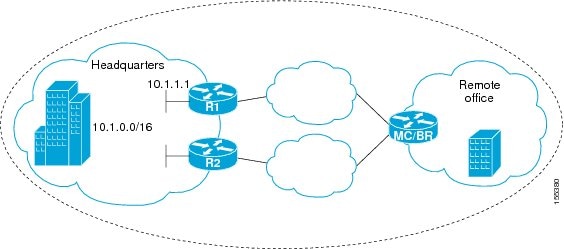
This configuration optimizes voice traffic to use the best performance path, whereas all other traffic destined to the same network—10.1.0.0/16—will follow the best path as indicated by a traditional routing protocol, for example BGP, that is configured on the device. As part of this optimization, OER will use policy based routing (PBR) to set the best exit link for voice traffic within a device.
The following configuration is performed on the edge router R1 in Figure 3 in the headquarters network to enable the IP SLAs Responder.
enable
configure terminal
ip sla responder
exit
The following configuration is performed on the edge router MC/BR (which is both an OER master controller and border router) in Figure 3 in the remote office network to optimize voice traffic using active probes.
enable
configure terminal
ip access-list extended Voice_Traffic
10 permit udp any 10.1.0.0 0.0.255.255 range 16384 32767
exit
oer-map Voice_MAP 10
match ip address access-list Voice_Traffic
set active-probe jitter 10.1.1.1 target-port 1025 codec g711alaw
set delay threshold 300
set mos threshold 3.76 percent 30
set jitter threshold 15
set loss relative 5
resolve mos priority 1
resolve jitter priority 2
resolve delay priority 3
resolve loss priority 4
Optimizing Traffic (Including Voice Traffic) Using Active Probes: Example
Figure 4 shows that traffic originating in the headquarters network and destined for the remote office network has to be optimized based on voice traffic metrics. Voice traffic is one of the most important traffic classes that travel from the headquarters to the remote office network, so the voice traffic must be prioritized to be optimized. Degradation in voice packet quality is less likely to be introduced within the network, so probing the edge of the network gives a measurement that is close to probing the final destination.
Figure 4 OER Network Topology for Optimizing All Traffic Using Active Probes
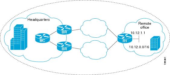
This configuration optimizes all traffic, including voice traffic, destined for the10.12.0.0/16 network. The OER optimization is based on the measurement of voice performance metrics with thresholding values using active probes. As part of the optimization, OER will introduce a BGP or a static route into the headquarters network. For more details about BGP and static route optimization, see the "Using OER to Control Traffic Classes and Verify the Route Control Changes" module.
The following configuration is performed on router R1 in Figure 4 in the remote office network to enable the IP SLAs Responder.
enable
configure terminal
ip sla responder
exit
The following configuration is performed on one of the BR routers in Figure 4 in the headquarters network to optimize all traffic (including voice traffic) using active probes.
enable
configure terminal
ip prefix-list All_Traffic_Prefix permit 10.12.0.0/16
oer-map Traffic_MAP 10
match ip address prefix-list All_Traffic_Prefix
set active-probe jitter 10.12.1.1 target-port 1025 codec g711alaw
! port 1025 for the target probe is an example.
set delay threshold 300
set mos threshold 3.76 percent 30
set jitter threshold 15
set loss relative 5
resolve mos priority 1
resolve jitter priority 2
resolve delay priority 3
resolve loss priority 4
Where to Go Next
This document describes a specific implementation of OER and presumes that you are familiar with the OER technology. If you want to review more information about OER, proceed to the Cisco IOS Optimized Edge Routing Overview module, followed by the Setting Up OER Network Components module. If you have set up your OER components, you should read through the other modules in the following list:
•![]() Using OER to Profile the Traffic Classes
Using OER to Profile the Traffic Classes
•![]() Measuring the Traffic Class Performance and Link Utilization Using OER
Measuring the Traffic Class Performance and Link Utilization Using OER
•![]() Configuring and Applying OER Policies
Configuring and Applying OER Policies
•![]() Using OER to Control Traffic Classes and Verify the Route Control Changes
Using OER to Control Traffic Classes and Verify the Route Control Changes
After you understand the various OER phases, review the OER solutions modules that are listed under "Related Documents" section.
Additional References
The following sections provide references related to optimizing voice traffic using OER active probes.
Related Documents
Cisco OER technology overview
"Cisco IOS Optimized Edge Routing Overview" module
Concepts and configuration tasks required to set up OER network components.
"Setting Up OER Network Components" module
OER solution module: configuring VPN IPsec/GRE tunnel interfaces as OER-managed exit links.
"Configuring VPN IPsec/GRE Tunnel Interfaces As OER-Managed Exit Links" module
Cisco OER commands: complete command syntax, command mode, command history, defaults, usage guidelines and examples
Cisco IOS Optimized Edge Routing Command Reference
IP Routing Protocol commands
Cisco IOS IP Routing Protocols Command Reference
Technical Assistance
The Cisco Support website provides extensive online resources, including documentation and tools for troubleshooting and resolving technical issues with Cisco products and technologies.
To receive security and technical information about your products, you can subscribe to various services, such as the Product Alert Tool (accessed from Field Notices), the Cisco Technical Services Newsletter, and Really Simple Syndication (RSS) Feeds.
Access to most tools on the Cisco Support website requires a Cisco.com user ID and password.
http://www.cisco.com/techsupport
Feature Information for OER Voice Traffic Optimization Using Active Probes
Table 1 lists the features in this module and provides links to specific configuration information. Only features that were introduced or modified in Cisco IOS Release 12.4(6)T, 12.2(33)SRB, or a later release appear in the table.
For information on a feature in this technology that is not documented here, see the "Cisco IOS Optimized Edge Routing Feature Roadmap."
Not all commands may be available in your Cisco IOS software release. For release information about a specific command, see the command reference documentation.
Use Cisco Feature Navigator to find information about platform support and software image support. Cisco Feature Navigator enables you to determine which Cisco IOS and Catalyst OS software images support a specific software release, feature set, or platform. To access Cisco Feature Navigator, go tohttp://www.cisco.com/go/cfn. An account on Cisco.com is not required.
Note![]() Table 1 lists only the Cisco IOS software release that introduced support for a given feature in a given Cisco IOS software release train. Unless noted otherwise, subsequent releases of that Cisco IOS software release train also support that feature.
Table 1 lists only the Cisco IOS software release that introduced support for a given feature in a given Cisco IOS software release train. Unless noted otherwise, subsequent releases of that Cisco IOS software release train also support that feature.
Table 1 Feature Information for OER Voice Traffic Optimization Using Active Probes
OER Voice Traffic Optimization
12.4(6)T
12.2(33)SRB
The OER Voice Traffic Optimization feature provides support for outbound optimization of voice traffic based on the voice metrics, jitter and Mean Opinion Score (MOS). Jitter and MOS are important quantitative quality metrics for voice traffic and these voice metrics are measured using OER active probes.
The following commands were introduced or modified by this feature: active-probe, jitter, mos, resolve, set active-probe, set jitter, set mos, set probe, set resolve, show oer master active-probes, show oer master policy, and show oer master prefix.
CCDE, CCENT, CCSI, Cisco Eos, Cisco HealthPresence, Cisco IronPort, the Cisco logo, Cisco Nurse Connect, Cisco Pulse, Cisco SensorBase, Cisco StackPower, Cisco StadiumVision, Cisco TelePresence, Cisco Unified Computing System, Cisco WebEx, DCE, Flip Channels, Flip for Good, Flip Mino, Flipshare (Design), Flip Ultra, Flip Video, Flip Video (Design), Instant Broadband, and Welcome to the Human Network are trademarks; Changing the Way We Work, Live, Play, and Learn, Cisco Capital, Cisco Capital (Design), Cisco:Financed (Stylized), Cisco Store, Flip Gift Card, and One Million Acts of Green are service marks; and Access Registrar, Aironet, AllTouch, AsyncOS, Bringing the Meeting To You, Catalyst, CCDA, CCDP, CCIE, CCIP, CCNA, CCNP, CCSP, CCVP, Cisco, the Cisco Certified Internetwork Expert logo, Cisco IOS, Cisco Lumin, Cisco Nexus, Cisco Press, Cisco Systems, Cisco Systems Capital, the Cisco Systems logo, Cisco Unity, Collaboration Without Limitation, Continuum, EtherFast, EtherSwitch, Event Center, Explorer, Follow Me Browsing, GainMaker, iLYNX, IOS, iPhone, IronPort, the IronPort logo, Laser Link, LightStream, Linksys, MeetingPlace, MeetingPlace Chime Sound, MGX, Networkers, Networking Academy, PCNow, PIX, PowerKEY, PowerPanels, PowerTV, PowerTV (Design), PowerVu, Prisma, ProConnect, ROSA, SenderBase, SMARTnet, Spectrum Expert, StackWise, WebEx, and the WebEx logo are registered trademarks of Cisco Systems, Inc. and/or its affiliates in the United States and certain other countries.
All other trademarks mentioned in this document or website are the property of their respective owners. The use of the word partner does not imply a partnership relationship between Cisco and any other company. (0910R)
Any Internet Protocol (IP) addresses and phone numbers used in this document are not intended to be actual addresses and phone numbers. Any examples, command display output, network topology diagrams, and other figures included in the document are shown for illustrative purposes only. Any use of actual IP addresses or phone numbers in illustrative content is unintentional and coincidental.
- OER Voice Traffic Optimization Using Active Probes
- Placing probes using scripting
- READING NOTE: Understanding intermediate layers using linear classifier probes
- myEvalSVC,2.2,Using traffic traces
- Isolating VM Traffic Using VLANs
- 机器学习:Colorization using Optimization
- Voice Recording/Playing back using simple classes
- Voice Conversion using Convolutional Neural Networks 翻译
- Search Engine Optimization -Building Traffic and Making Money with SEO
- Identifying P2P users using traffic analysis
- OER 7451
- Code Optimization Using the GNU C Compiler
- Kernel Probes
- light probes
- how to program using ROCKWELL's Voice/Fax/Data
- Security Onion Searching DNS Traffic using Bro and ELSA
- Using Forms Authentication with Active Directory
- Query Active Directory Users using C#
- linux命令 sync
- 南阳 139 我排第几个
- IE6查看ActiveX控件是否已经安装以及版本号
- Error using pdist2 Too many input arguments
- NSAttributedString详解
- OER Voice Traffic Optimization Using Active Probes
- Linux下nm和ldd 命令
- Cocos2d-x 弹出对话框的设计与实现
- 去除List中重复元素
- Js实现短信发送进度条
- poj 3370 Halloween treats
- vc++提示cannot open include file 'afxres.h'———VC安装设置问题
- Cos上传
- @Repository、@Service、@Controller 和 @Component