OpenGL ES From the Ground Up, Part 3: Viewports in Perspective
来源:互联网 发布:新浪微博淘宝店铺认证 编辑:程序博客网 时间:2024/05/16 05:03
SATURDAY, APRIL 25, 2009
OpenGL ES From the Ground Up, Part 3: Viewports in Perspective
Now that you got a taste of how to draw in OpenGL, let's take a step back and talk about something very important: the OpenGL viewport. Many people who are new to 3D programming, but who have worked with 3D graphics programs like Maya, Blender, or Lightwave, expect to find an object in OpenGL's virtual world called a "camera". There is no such beast. What there is, is a defined chunk of 3D space that can be seen. The virtual world is infinite, but computers don't deal well with infinite, so OpenGL asks us to define a chunk of space that can be seen by the viewer.
If we think of it in terms of the camera object that most 3D programs have, the middle of one end of the viewport is the camera. It's the point at which the viewer is standing. It's a virtual window into the virtual world. There is a certain amount of space that the viewer can see. She can't see stuff behind her. She can't see things outside of her angle of view. And she can't see things that are too far away. Think of the viewport as a shape determined by the parameters "what the viewer can see". That seems pretty straightforward, right?
Unfortunately, it is not. To explain why, we first need to talk about the fact that there are two different types of viewports that you can create in OpenGL ES: orthographic and perspective.
To understand this better, let's talk about railroad tracks, okay? Now, the two rails of a railroad track, in order to function correctly, have to be exactly a certain, unwavering distance apart. The exact distance varies with where the tracks are, and what type of train rides on them, but it's important that the rails (and the wheels on the train) be the same distance apart. If that weren't the case, trains simply wouldn't be able to function.
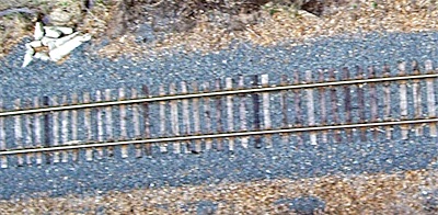
This fact is obvious if you look at railroad tracks from above.
But what happens if you stand on the railroad tracks and look down them. Don't say "you get hit by the train", I'm assuming you're smart enough to do this when the train's not coming.
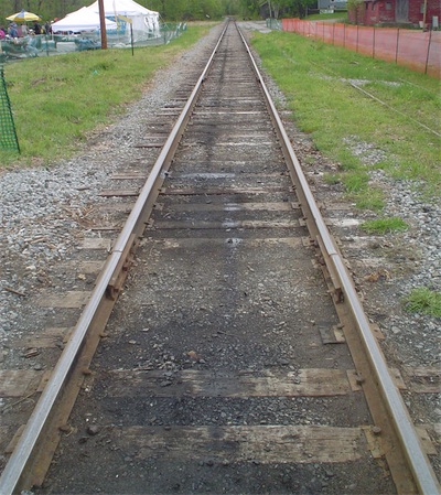
Yeah, the tracks look like they get closer as they move away from us. That, as you're probably well aware thanks to your second grade art teacher, is due to something called perspective.
One of the two ways that OpenGL viewports can be set up is to use perspective. When you set up a viewport this way, objects will get smaller as they move away, and lines will converge as they move away from the viewer. This will simulate real vision; the way people see things in the real world.
The other way you can set up a view port is called an orthogonal viewport. In this type of viewport, lines never converge and things don't change in size. There is no perspective. This is handy for CAD programs and a number of other purposes, but it doesn't look real, because that's not the way our eyes work, so it's not usually what you want.
With an orthogonal viewport, you can put your virtual camera on the railroad tracks, but those rails will never converge. They will stay the same distance apart as they move away from you. Even if you defined an infinitely large viewport (which you can't do in OpenGL ES) those lines would stay the same distance apart.
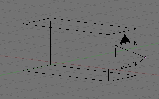
The nice thing about orthogonal viewports is that they are easy to define. Since lines never diverge, you just define a chunk of the 3D world that looks like a box, like this:
You can tell OpenGL ES that you want to set up an orthogonal viewport by using the function glOrthof() before you set declare your viewport using theglViewport() function. Here's a simple example:
That's not really too difficult to understand. We first get our view's size. We make our chunk of space we're looking into two units wide, running from -1.0 to +1.0 on the x-axis. Easy enough.
Then, what's going on with the Bottom and Top? Well, we want the X and Y coordinates of our chunk of space to have the same aspect ratio as our view (which, in a full-screen app is the aspect ratio of the iPhone's screen). Since the iPhone's width and height are different, we need to make sure the x and y coordinates of our view are different also, in the same proportion.
After that, we define a near and far limit to delineate the depth of our viewing volume. The near parameter is where the viewport starts. If we're standing on the origin, the viewport starts right in front of it, so it's customary to use .01 or .001 as the start of an orthogonal viewport. This starts it a tiny fraction in "front" of the origin. The far coordinate can be set based on the needs of the application you're writing. If you'll never have an object further away than 20 units, you don't need to set a far of 20,000 units. Exactly what number you use is going to vary from program to program.
After the call to glOrthof(), we call glViewport() with the view's rectangle, and we're done.
That was the easy case.
Notice that as we move away from the viewpoint (in other words, as the value of z decreases), the viewing volume gets larger on both the x and y coordinates.
To set up a perspective viewport, we don't use glOrthof(), we use a different function called glFrustumf(). This method takes the same six parameters. That's easy enough to understand, but how do we figure out what numbers to pass into glFrustumf()?
Well, near and far are easy. You figure them out the same way. Use something like .001 for near, and then base far on the needs of your specific program.
But what about left, right, bottom, and top. To set those, we're going to need to do a little bit of math.
To calculate our frustum, we need to first figure out our field of vision, which is defined by two angles. Let's do this: Stick both of yours arm out straight in front of you, palms together. Your arms are now pointing down the z axis of your own personal frustum, right? Okay, now, move your hands apart slowly. Because your shoulders stay in the same position as your hands move apart, you're defining an increasingly large angle. This is one of the two angles that defines your own viewing frustum. This is the angle that defines the width of your field of view, the other would be if you did exactly the same thing but moved your apart up and down as opposed to left and right.. If your hands are three inches apart, the x-angle is pretty small.
A narrow field of vision.
If you move them two feet apart, you create a much wider angle, and a wider field of vision.
A wide field of vision.
If you're into photography, you can think of field of vision as the focal length of our virtual camera's virtual lens. A narrow field of vision is much like a telephoto lens, creating a long frustum that tapers slowly. A wide field of vision is like a wide angle lens and creates a frustum that increases in size much faster.
Let's pick a nice middle-of-the road value to start, say 45°. Now that we have this value, how do we use it to calculate our viewing frustum? Well, let's look at one of the two angles. Imagine, if you will, what the frustum looks like from the top. Heck, you don't have to imagine, here's a diagram:
Okay, from above, it looks kinda like a triangle, with just a little bit of one point lopped of, doesn't it? Well, it's close enough to a triangle for our purposes. Now, do you remember tangents from trig class? The tangent function is defined as the ratio of the opposite leg of a right triangle to the adjacent leg.
Okay, but we don't have a right triangle, do we?
Actually, we have two… if we draw a line right down the z axis:
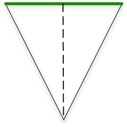
That dotted line down the center is the "adjacent leg" of the two right triangles we just created by drawing that line. So, half of the width of the far end of the frustum is the tangent of half of the angle of our field of view. If we take that value and multiply it by the near value, we have the value to pass as right. We pass the inverse of that number as left.
We want our field of view to have the same aspect ratio as the screen, so we can calculate the top and bottom values exactly as we did with glOrthof() - by multiplying the right value by the screen's aspect ratio. In code, that would look like this:
Let's see it in action. I modified the final drawView: method from the last posting so that instead of one icosahedron, it shows thirty icosahedrons extending down the z axis. Here is the new drawView: method.
If you drop this code into a project created from OpenGL project template for Xcode, which sets up a perspective viewport using glFrustumf() with a 45° field of vision, you get something that looks like this:
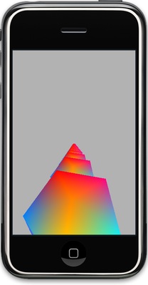
Nice, right? They get smaller as they go away from you, very similar in appearance to those train tracks as they move away from you.
If we do nothing other than change the glFrustumf() call to a glOrthof() call, it looks much different:
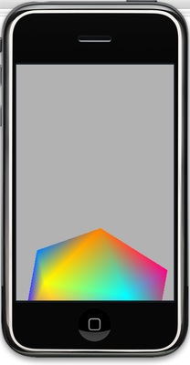
Without perspective, the twenty-nine icosahedrons behind the first one are obscured by the first. There's no perspective, so each shape lies exactly behind the one in front of it on the z axis.
Okay, that was a heavy topic, and the truth of the matter is you can forget all about the trig now. Just copy the two lines of code that calculate a frustum based on an field of vision angle, and you will probably never need to remember why it works.
In the next installment, we're going to shine some light on our icosahedron and make it look like a real, honest-to-goodness three-dimensional shape rather than a colorful, but flat object.

If we think of it in terms of the camera object that most 3D programs have, the middle of one end of the viewport is the camera. It's the point at which the viewer is standing. It's a virtual window into the virtual world. There is a certain amount of space that the viewer can see. She can't see stuff behind her. She can't see things outside of her angle of view. And she can't see things that are too far away. Think of the viewport as a shape determined by the parameters "what the viewer can see". That seems pretty straightforward, right?
Unfortunately, it is not. To explain why, we first need to talk about the fact that there are two different types of viewports that you can create in OpenGL ES: orthographic and perspective.
Orthographic vs. Perspective
To understand this better, let's talk about railroad tracks, okay? Now, the two rails of a railroad track, in order to function correctly, have to be exactly a certain, unwavering distance apart. The exact distance varies with where the tracks are, and what type of train rides on them, but it's important that the rails (and the wheels on the train) be the same distance apart. If that weren't the case, trains simply wouldn't be able to function.
This fact is obvious if you look at railroad tracks from above.
But what happens if you stand on the railroad tracks and look down them. Don't say "you get hit by the train", I'm assuming you're smart enough to do this when the train's not coming.
Yeah, the tracks look like they get closer as they move away from us. That, as you're probably well aware thanks to your second grade art teacher, is due to something called perspective.
One of the two ways that OpenGL viewports can be set up is to use perspective. When you set up a viewport this way, objects will get smaller as they move away, and lines will converge as they move away from the viewer. This will simulate real vision; the way people see things in the real world.
The other way you can set up a view port is called an orthogonal viewport. In this type of viewport, lines never converge and things don't change in size. There is no perspective. This is handy for CAD programs and a number of other purposes, but it doesn't look real, because that's not the way our eyes work, so it's not usually what you want.
With an orthogonal viewport, you can put your virtual camera on the railroad tracks, but those rails will never converge. They will stay the same distance apart as they move away from you. Even if you defined an infinitely large viewport (which you can't do in OpenGL ES) those lines would stay the same distance apart.
The nice thing about orthogonal viewports is that they are easy to define. Since lines never diverge, you just define a chunk of the 3D world that looks like a box, like this:
Setting up an Orthogonal Viewport
You can tell OpenGL ES that you want to set up an orthogonal viewport by using the function glOrthof() before you set declare your viewport using theglViewport() function. Here's a simple example:
CGRect rect = view.bounds; // FarThat's not really too difficult to understand. We first get our view's size. We make our chunk of space we're looking into two units wide, running from -1.0 to +1.0 on the x-axis. Easy enough.
Then, what's going on with the Bottom and Top? Well, we want the X and Y coordinates of our chunk of space to have the same aspect ratio as our view (which, in a full-screen app is the aspect ratio of the iPhone's screen). Since the iPhone's width and height are different, we need to make sure the x and y coordinates of our view are different also, in the same proportion.
After that, we define a near and far limit to delineate the depth of our viewing volume. The near parameter is where the viewport starts. If we're standing on the origin, the viewport starts right in front of it, so it's customary to use .01 or .001 as the start of an orthogonal viewport. This starts it a tiny fraction in "front" of the origin. The far coordinate can be set based on the needs of the application you're writing. If you'll never have an object further away than 20 units, you don't need to set a far of 20,000 units. Exactly what number you use is going to vary from program to program.
After the call to glOrthof(), we call glViewport() with the view's rectangle, and we're done.
That was the easy case.
Setting up the Perspective Viewport
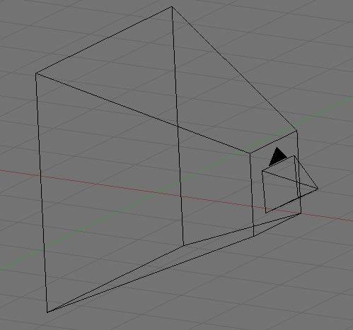
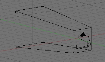
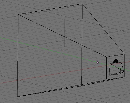
The other case is not quite as simple, and here's why. If objects get smaller as they move away from you, what does that do to the shape of the chunk of space you can see. You can see more of the world that's further away from you, so the chunk of space you need to define isn't a cube if you're using perspective. No, the shape of the space you can see when using perspective is called a frustum. Yeah, I know. Strange word, right? But it's a real thing. Our frustum will look something like this:Notice that as we move away from the viewpoint (in other words, as the value of z decreases), the viewing volume gets larger on both the x and y coordinates.
To set up a perspective viewport, we don't use glOrthof(), we use a different function called glFrustumf(). This method takes the same six parameters. That's easy enough to understand, but how do we figure out what numbers to pass into glFrustumf()?
Well, near and far are easy. You figure them out the same way. Use something like .001 for near, and then base far on the needs of your specific program.
But what about left, right, bottom, and top. To set those, we're going to need to do a little bit of math.
To calculate our frustum, we need to first figure out our field of vision, which is defined by two angles. Let's do this: Stick both of yours arm out straight in front of you, palms together. Your arms are now pointing down the z axis of your own personal frustum, right? Okay, now, move your hands apart slowly. Because your shoulders stay in the same position as your hands move apart, you're defining an increasingly large angle. This is one of the two angles that defines your own viewing frustum. This is the angle that defines the width of your field of view, the other would be if you did exactly the same thing but moved your apart up and down as opposed to left and right.. If your hands are three inches apart, the x-angle is pretty small.
If you move them two feet apart, you create a much wider angle, and a wider field of vision.
If you're into photography, you can think of field of vision as the focal length of our virtual camera's virtual lens. A narrow field of vision is much like a telephoto lens, creating a long frustum that tapers slowly. A wide field of vision is like a wide angle lens and creates a frustum that increases in size much faster.
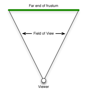
Let's pick a nice middle-of-the road value to start, say 45°. Now that we have this value, how do we use it to calculate our viewing frustum? Well, let's look at one of the two angles. Imagine, if you will, what the frustum looks like from the top. Heck, you don't have to imagine, here's a diagram:
Okay, from above, it looks kinda like a triangle, with just a little bit of one point lopped of, doesn't it? Well, it's close enough to a triangle for our purposes. Now, do you remember tangents from trig class? The tangent function is defined as the ratio of the opposite leg of a right triangle to the adjacent leg.
Okay, but we don't have a right triangle, do we?
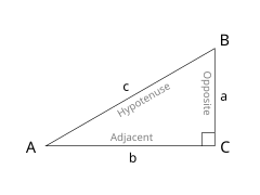
Actually, we have two… if we draw a line right down the z axis:
That dotted line down the center is the "adjacent leg" of the two right triangles we just created by drawing that line. So, half of the width of the far end of the frustum is the tangent of half of the angle of our field of view. If we take that value and multiply it by the near value, we have the value to pass as right. We pass the inverse of that number as left.
We want our field of view to have the same aspect ratio as the screen, so we can calculate the top and bottom values exactly as we did with glOrthof() - by multiplying the right value by the screen's aspect ratio. In code, that would look like this:
CGRect rect = view.bounds; GLfloat size = .01 * // FarNote: A discussion of how glFrustum() uses the passed parameters to calculate the shape of the frustum going to have to wait until we've discussed matrices. For now, just take it on faith that this calculation works, okay?
Let's see it in action. I modified the final drawView: method from the last posting so that instead of one icosahedron, it shows thirty icosahedrons extending down the z axis. Here is the new drawView: method.
- (void)drawView:(GLView*)view;If you drop this code into a project created from OpenGL project template for Xcode, which sets up a perspective viewport using glFrustumf() with a 45° field of vision, you get something that looks like this:
Nice, right? They get smaller as they go away from you, very similar in appearance to those train tracks as they move away from you.
If we do nothing other than change the glFrustumf() call to a glOrthof() call, it looks much different:
Without perspective, the twenty-nine icosahedrons behind the first one are obscured by the first. There's no perspective, so each shape lies exactly behind the one in front of it on the z axis.
Okay, that was a heavy topic, and the truth of the matter is you can forget all about the trig now. Just copy the two lines of code that calculate a frustum based on an field of vision angle, and you will probably never need to remember why it works.
Stay tuned for next week's exciting adventure…
In the next installment, we're going to shine some light on our icosahedron and make it look like a real, honest-to-goodness three-dimensional shape rather than a colorful, but flat object.
0 0
- OpenGL ES From the Ground Up, Part 3: Viewports in Perspective
- OpenGL ES From the Ground Up, Part 1: Basic Concepts
- OpenGL ES From the Ground Up, Part 5: Living in a Material World
- OpenGL ES From the Ground Up, Part 6: Textures and Texture Mapping
- OpenGL ES From the Ground Up, Part 4: Let There Be Light!
- OpenGL ES From the Ground Up, Part 2: A Look at Simple Drawing
- OpenGL ES From the Ground Up, Part 1 Addendum: Alphabet Soup
- Essential ActionScript 3.0 Part ⅠActionScript from the Ground Up Review
- Book - Programming from the Ground Up
- Programming from the ground up(0)
- 总结《Ray Tracing from the Ground Up》
- OpenGL ES Tutorial for Android – Part I – Setting up the view
- OpenGL ES Tutorial for Android – Part I – Setting up the view
- OpenGL ES Tutorial for Android – Part I – Setting up the view
- OpenGL ES Tutorial for Android – Part I – Setting up the view
- 深入REDIS,读REDIS-FROM-THE-GROUND-UP有感
- 【Ray Tracing from Ground Up】DRBF
- 【Ray Tracing from Ground Up】阴影 (Shadow)
- 关于手机的基站
- OpenGL ES From the Ground Up, Part 4: Let There Be Light!
- hadoop 安装 配置 平台搭建
- IOS即时聊天UI设计
- 在string中取单词的程序。。。2014.5.7
- OpenGL ES From the Ground Up, Part 3: Viewports in Perspective
- 中山大学 CSU 1394
- class sizeof
- 第六章的例题
- android从res、assets中读取文件
- Sizeof与Strlen的区别与联系
- 【opencv】kmeans
- 【Linux学习】Ubuntu下内核编译(一)
- 逆序数poj 2299 Ultra-QuickSort sgu 180 Inversions