2.2.4 Silhouette Enhancement (about transforming normal vectors) 轮廓增强(关于转换法向量)
来源:互联网 发布:ios放置类游戏 知乎 编辑:程序博客网 时间:2024/06/09 09:16

A semitransparent jellyfish. Note the increased opaqueness at the silhouettes.
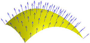
Surface normal vectors (for short: normals) on a surface patch.
This tutorial covers thetransformation of surface normal vectors. It assumes that you are familiar with alpha blending as discussed inSection “Transparency” and with shader properties as discussed in Section “Shading in World Space”.
The objective of this tutorial is to achieve an effect that is visible in the photo to the left: the silhouettes of semitransparent objects tend to be more opaque than the rest of the object. This adds to the impression of a three-dimensional shape even without lighting. It turns out that transformed normals are crucial to obtain this effect.
Silhouettes of Smooth Surfaces
In the case of smooth surfaces, points on the surface at silhouettes are characterized by normal vectors that are parallel to the viewing plane and therefore orthogonal to the direction to the viewer. In the figure to the left, the blue normal vectors at the silhouette at the top of the figure are parallel to the viewing plane while the other normal vectors point more in the direction to the viewer (or camera). By calculating the direction to the viewer and the normal vector and testing whether they are (almost) orthogonal to each other, we can therefore test whether a point is (almost) on the silhouette.
More specifically, ifV is the normalized (i.e. of length 1) direction to the viewer andN is the normalized surface normal vector, then the two vectors are orthogonal if the dot product is 0:V·N = 0. In practice, this will rarely be the case. However, if the dot productV·N is close to 0, we can assume that the point is close to a silhouette.
Increasing the Opacity at Silhouettes
For our effect, we should therefore increase the opacity if the dot productV·N is close to 0. There are various ways to increase the opacity for small dot products between the direction to the viewer and the normal vector. Here is one of them (which actually has a physical model behind it, which is described in Section 5.1 of this publication) to compute the increased opacity
  from the regular opacity of the material:

It always makes sense to check the extreme cases of an equation like this. Consider the case of a point close to the silhouette:V·N ≈ 0. In this case, the regular opacity will be divided by a small, positive number. (Note that GPUs usually handle the case of division by zero gracefully; thus, we don't have to worry about it.) Therefore, whatever is, the ratio of and a small positive number, will be larger. The function will take care that the resulting opacity is never larger than 1.
On the other hand, for points far away from the silhouette we haveV·N ≈ 1. In this case, α' ≈ min(1, α) ≈ α; i.e., the opacity of those points will not change much. This is exactly what we want. Thus, we have just checked that the equation is at least plausible.
Implementing an Equation in a Shader
In order to implement an equation like the one for in a shader, the first question should be: Should it be implemented in the vertex shader or in the fragment shader? In some cases, the answer is clear because the implementation requires texture mapping, which is often only available in the fragment shader. In many cases, however, there is no general answer. Implementations in vertex shaders tend to be faster (because there are usually fewer vertices than fragments) but of lower image quality (because normal vectors and other vertex attributes can change abruptly between vertices). Thus, if you are most concerned about performance, an implementation in a vertex shader is probably a better choice. On the other hand, if you are most concerned about image quality, an implementation in a fragment shader might be a better choice. The same trade-off exists between per-vertex lighting (i.e. Gouraud shading, which is discussed inSection “Specular Highlights”) and per-fragment lighting (i.e. Phong shading, which is discussed inSection “Smooth Specular Highlights”).
The next question is: in which coordinate system should the equation be implemented? (SeeSection “Vertex Transformations” for a description of the standard coordinate systems.) Again, there is no general answer. However, an implementation in world coordinates is often a good choice in Unity because many uniform variables are specified in world coordinates. (In other environments implementations in view coordinates are very common.)
The final question before implementing an equation is: where do we get the parameters of the equation from? The regular opacity is specified (within a RGBA color) by a shader property (seeSection “Shading in World Space”). The normal vector normal is a standard vertex input parameter (seeSection “Debugging of Shaders”). The direction to the viewer can be computed in the vertex shader as the vector from the vertex position in world space to the camera position in world space_WorldSpaceCameraPos, which is provided by Unity.
Thus, we only have to transform the vertex position and the normal vector into world space before implementing the equation. The transformation matrix_Object2World from object space to world space and its inverse _World2Object are provided by Unity as discussed in Section “Shading in World Space”. The application of transformation matrices to points and normal vectors is discussed in detail inSection “Applying Matrix Transformations”. The basic result is that points and directions are transformed just by multiplying them with the transformation matrix, e.g. withmodelMatrix set to _Object2World:
output.viewDir = normalize(_WorldSpaceCameraPos - mul(modelMatrix, input.vertex).xyz);On the other handnormal vectors are transformed by multiplying them with the transposed inverse transformation matrix. Since Unity provides us with the inverse transformation matrix (which is
_World2Object), a better alternative is to multiply the normal vectorfrom the left to the inverse matrix, which is equivalent to multiplying it from the right to the transposed inverse matrix as discussed inSection “Applying Matrix Transformations”:output.normal = normalize( mul(float4(input.normal, 0.0), modelMatrixInverse).xyz);
Now we have all the pieces that we need to write the shader.
Shader Code
Shader "Cg silhouette enhancement" { Properties { _Color ("Color", Color) = (1, 1, 1, 0.5) // user-specified RGBA color including opacity } SubShader { Tags { "Queue" = "Transparent" } // draw after all opaque geometry has been drawn Pass { ZWrite Off // don't occlude other objects Blend SrcAlpha OneMinusSrcAlpha // standard alpha blending CGPROGRAM #pragma vertex vert #pragma fragment frag #include "UnityCG.cginc" uniform float4 _Color; // define shader property for shaders struct vertexInput { float4 vertex : POSITION; float3 normal : NORMAL; }; struct vertexOutput { float4 pos : SV_POSITION; float3 normal : TEXCOORD; float3 viewDir : TEXCOORD1; }; vertexOutput vert(vertexInput input) { vertexOutput output; float4x4 modelMatrix = _Object2World; float4x4 modelMatrixInverse = _World2Object; output.normal = normalize(mul(float4(input.normal, 0.0), modelMatrixInverse).xyz); output.viewDir = normalize(_WorldSpaceCameraPos - mul(modelMatrix, input.vertex).xyz); output.pos = mul(UNITY_MATRIX_MVP, input.vertex); return output; } float4 frag(vertexOutput input) : COLOR { float3 normalDirection = normalize(input.normal); float3 viewDirection = normalize(input.viewDir); float newOpacity = min(1.0, _Color.a / abs(dot(viewDirection, normalDirection))); return float4(_Color.rgb, newOpacity); } ENDCG } }}The assignment to newOpacity is an almost literal translation of the equation

Note that we normalize the vertex output parametersoutput.normal and output.viewDir in the vertex shader (because we want to interpolate between directions without putting more nor less weight on any of them) and at the begin of the fragment shader (because the interpolation can distort our normalization to a certain degree). However, in many cases the normalization ofoutput.normal in the vertex shader is not necessary. Similarly, the normalization ofoutput.viewDir in the fragment shader is in most cases unnecessary.
More Artistic Control
While the described silhouette enhancement is based on a physical model, it lacks artistic control; i.e., a CG artist cannot easily create a thinner or thicker silhouette than the physical model suggests. To allow for more artistic control, you could introduce another (positive) floating-point number property and take the dot product |V·N| to the power of this number (using the built-in Cg functionpow(float x, float y)) before using it in the equation above. This will allow CG artists to create thinner or thicker silhouettes independently of the opacity of the base color.
Summary
Congratulations, you have finished this tutorial. We have discussed:
- How to find silhouettes of smooth surfaces (using the dot product of the normal vector and the view direction).
- How to enhance the opacity at those silhouettes.
- How to implement equations in shaders.
- How to transform points and normal vectors from object space to world space (using the transposed inverse model matrix for normal vectors).
- How to compute the viewing direction (as the difference from the camera position to the vertex position).
- How to interpolate normalized directions (i.e. normalize twice: in the vertex shader and the fragment shader).
- How to provide more artistic control over the thickness of silhouettes .
Further Reading
If you still want to know more
- about object space and world space, you should read the description inSection “Vertex Transformations”.
- about how to apply transformation matrices to points, directions and normal vectors, you should readSection “Applying Matrix Transformations”.
- about the basics of rendering transparent objects, you should readSection “Transparency”.
- about uniform variables provided by Unity and shader properties, you should readSection “Shading in World Space”.
- about the mathematics of silhouette enhancement, you could read Section 5.1 of the paper “Scale-Invariant Volume Rendering” by Martin Kraus, published at IEEE Visualization 2005, which is availableonline.
- 2.2.4 Silhouette Enhancement (about transforming normal vectors) 轮廓增强(关于转换法向量)
- Cg Programming/Unity/Silhouette Enhancement轮廓增强
- 点和向量的转换 Transforming Points and Vectors
- Cg silhouette enhancement
- Mathematics for 3D Game Programming and Computer Graphics - Transforming Normal Vectors
- 聚类评估算法-轮廓系数(Silhouette Coefficient )
- 版本向量(version vectors)
- 学习下c++中的向量(Vectors)
- SAP 增强(Enhancement)(转)
- Qt 3D的研究(十):描边渲染(轮廓渲染)以及Silhouette Shader
- About ELF Auxiliary Vectors
- 表格增强 FIELD ENHANCEMENT
- Enhancement spot 增强点
- 代码增强(Code Enhancement)
- 函数增强(Function Enhancement )
- SAP 增强(Enhancement)之----基本结构和概念
- 将图像转换为特征向量Transforming Images to Feature Vectors
- About normal map
- 面试题28:字符串的排列
- MDA模型驱动
- 卡兰特数列 解决出栈序列统计问题
- 运行时和常见面试题目
- 欧拉回路
- 2.2.4 Silhouette Enhancement (about transforming normal vectors) 轮廓增强(关于转换法向量)
- HDU 4940 - Destroy Transportation system(网络流)
- ADAS在车载导航设备上的应用
- OC/Swift基本控件(针对入门级别程序猿)--上
- OpenCV 3.0.0+contrib+VS2013配置方法
- Android 控件之一:Button 按钮
- iOS FMDB
- 学习Java语言的小技巧
- 关于SAPI的两段小代码(c++)