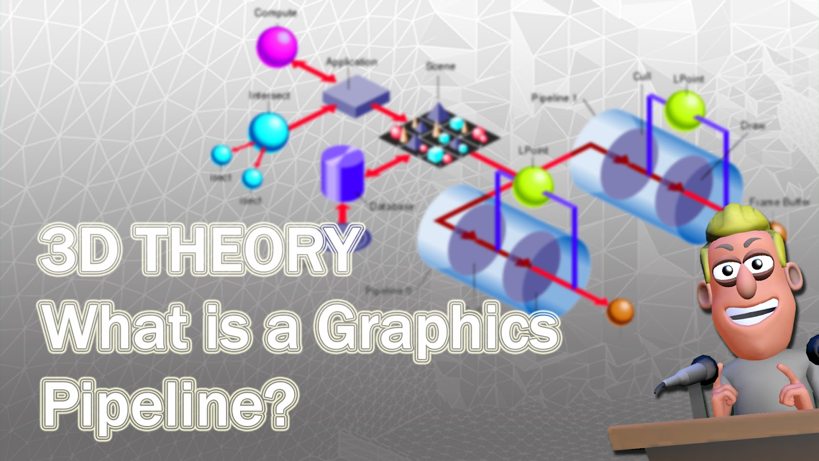
Graphics Pipelines
来源:互联网 发布:mac怎么压缩图片 编辑:程序博客网 时间:2024/04/30 15:11
Graphics Pipelines
This is asmart resource. Use a QR readeror theAurasmaapp to access additional content.
https://goo.gl/vyCH2Q

Introduction: What is a graphics pipeline?
The graphics pipeline is an important concept in computer graphics and it refers to the process of different stages that is used to turn the instructions on a computer into graphics on a screen.
Each API has its own pipeline but the stages used are similar as are the final results. So in order to explore the different stages within a pipeline we’ll take a look at DirectX 11.

Here’s a simplified flowchart of the stages of the pipeline. As you can see the different stages are; Input assembler, Vertex shader, Hull shader, Tessellator, Domain Shader, Geometry Shader, Rasterizer, Pixel Shader and Output Merger.
The first stage in the pipeline is the Input Assembler. This can be thought of as the building block stage. At this stage the geometry is built so that it can be rendered out later in the process.
The second stage is the vertex shader. Here is code is run that operates on each of the vertices, this generally means applying shaders. These vertices have come from the input assembler stage.
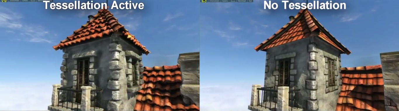
The third, fourth and fifth stages are optional and deal with tessellation. Hardware tessellation is the process of taking the original geometry and increasing or decreasing the level of detail by adding or removing faces. This means that if the hardware is powerful enough shapes can be made smoother and more detailed in real time. Here’s an example of tessellation in use.
http://goo.gl/X9iqwm

In the image on the left you can see that the geometry is much more detailed than in the image on the right.
The sixth stage is the geometry shader and this is also an optional shader stage. Geometry shaders operate on entire shapes such as triangles and not just on vertices like with the vertex shader. At the geometry shader stage geometry can be created or destroyed as needed depending on the effect the developer is trying to create. Uses here include the generation of particles used to create effects such as rain or explosions.
The seventh stage, the rasterizer, determines what pixels are visible through clipping and culling geometry. Culling is where any geometry that does not fall within the dimensions of the rectangle representing the screen (known as the view frustum) is discarded. Clipping is where any geometry that lies partly of the view frustum is clipped and reshaped with new triangles. This stage then sets up the pixel shaders and sorts out how they will be applied.
The eighth stage is the pixel shader stage. Here the geometry is taken from the previous stages and the pixels (often referred to as fragments because pixels are what is output on the screen) are shaded to comprise the shapes.
The output merger is the final stage in the pipeline and this is where everything from the previous stages all comes together. The final image is built using the data calculated in the earlier steps and is sent to the screen.
The staggering thing about this complicated process is that, if a game is running at 30 frames per second, then the data is sent through this pipeline 30 times every second!
- Graphics Pipelines
- iOS vs. Android ICS: Hardware Accelerated Graphics Pipelines
- Data Pipelines
- ML Pipelines
- graphics
- Graphics
- Graphics
- Graphics
- graphics
- graphics
- Graphics
- Graphics
- Graphics
- Graphics
- Graphics
- Graphics
- Graphics
- zoj 2710 Two Pipelines
- struts2中的constant详解
- Level of detail
- Android自定义页面指示器
- 数据结构和算法经典100题-第27题
- 刚安装的sql server 无法附加数据库
- Graphics Pipelines
- U盘安装win7sp1,在USB3.0接口上需要驱动
- 链接太长自动换行
- 多线程之线程创建的两种方法(Java)
- Object源码后记
- iOS问题(iOS9 + Xcode7)
- activiti流程设计器activiti designer在eclipse中的安装。
- Geometric Theory for 3D Graphics
- Android头像缓存