1-Computer Networks and the Internet
来源:互联网 发布:为什么淘宝退款打不开 编辑:程序博客网 时间:2024/05/02 03:11
Please indicate the source: http://blog.csdn.net/gaoxiangnumber1
Welcome to my github: https://github.com/gaoxiangnumber1
1.1 What Is the Internet?
1.1.1 A Nuts-and-Bolts Description
- When one end system has data to send to another end system, the sending end system segments the data and adds header bytes to each segment. The resulting packages of information, known as packets, are then sent through the network to the destination end system, where they are reassembled into the original data.
- A packet switch takes a packet arriving on one of its incoming communication links and forwards that packet on one of its outgoing communication links. Packet switches have two main types: link-layer switches and routers. Both types of switches forward packets toward their ultimate destinations.
Link-layer switches are typically used in access networks, while routers are typically used in the network core. - The sequence of communication links and packet switches traversed by a packet from the sending end system to the receiving end system is a route or path through the network.
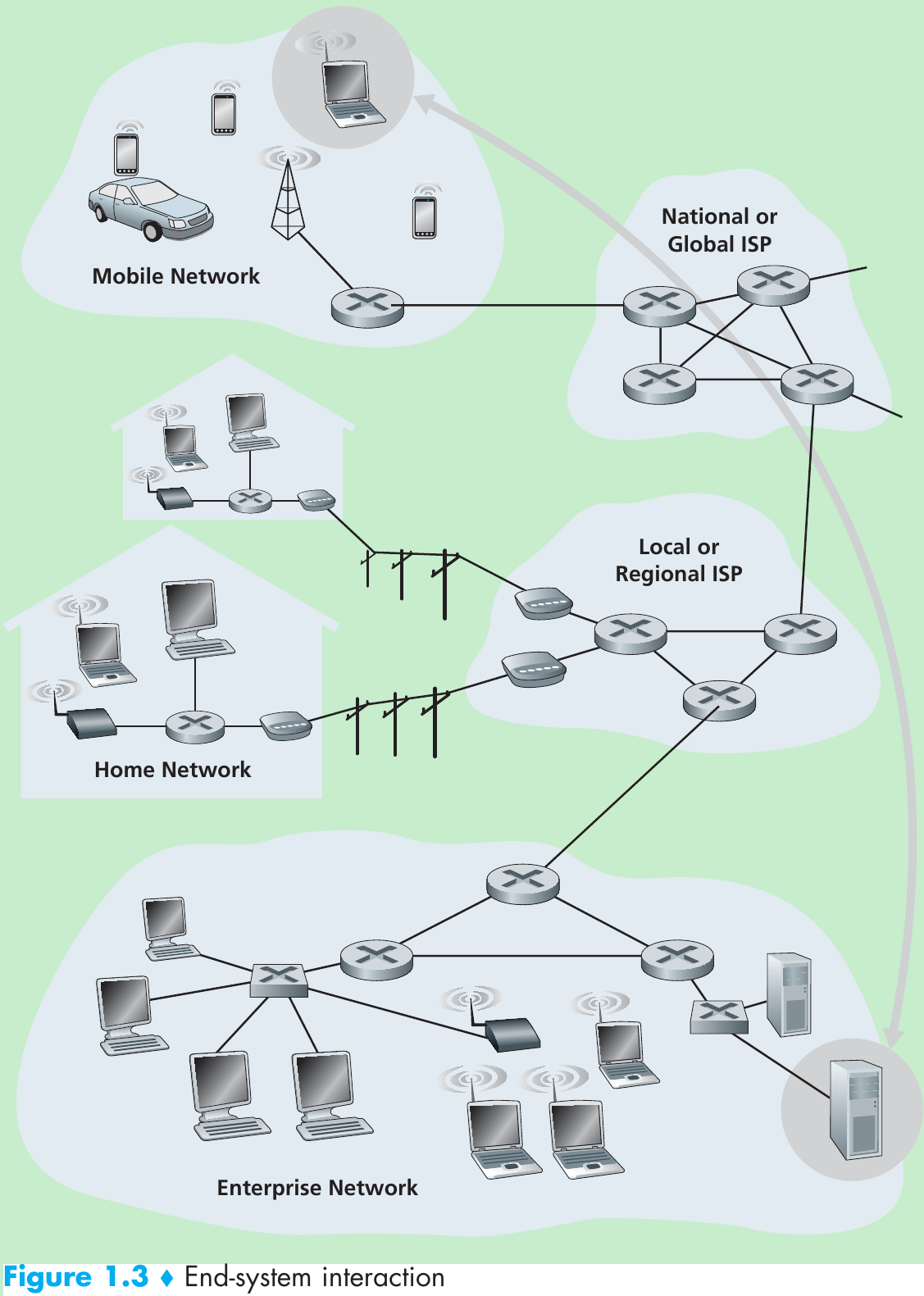
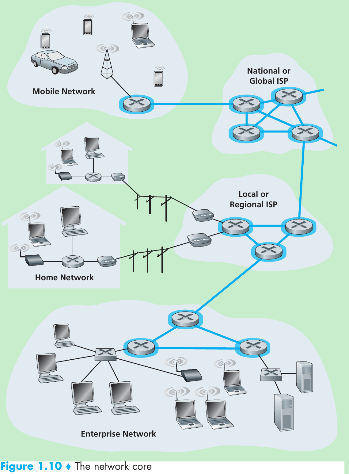
- End systems access the Internet through Internet Service Providers (ISPs). Each ISP is in itself a network of packet switches and communication links. ISPs provide a variety of types of network access to the end systems and provide Internet access to content providers, connecting Web sites directly to the Internet.
- Lower-tier ISPs are interconnected through national and international upper-tier ISPs such as AT&T. Each ISP network is managed independently, runs the IP protocol, and conforms to certain naming and address conventions.
- End systems, packet switches, and other pieces of the Internet run protocols that control the sending and receiving of information within the Internet. The Transmission Control Protocol (TCP) and the Internet Protocol (IP) are two of the most important protocols in the Internet. The IP protocol specifies the format of the packets that are sent and received among routers and end systems. The Internet’s principal protocols are collectively known as TCP/IP.
- Internet standards are developed by the Internet Engineering Task Force (IETF). The IETF standards documents are called requests for comments (RFCs). RFCs started out as general requests for comments to resolve network and protocol design problems that faced the precursor to the Internet. They define protocols such as TCP, IP, HTTP (for the Web), and SMTP (for e-mail).
1.1.2 A Services Description
1.1.3 What Is a Protocol?

- All activity in the Internet that involves two or more communicating remote entities is governed by a protocol.
- A protocol defines the format and the order of messages exchanged between two or more communicating entities, and the actions taken on the transmission and/or receipt of a message or other event.
1.2 The Network Edge
- End systems are also referred to as hosts because they host (run) application programs such as a Web browser program. that is, host = end system. Hosts are further divided into two categories: clients and servers. Clients tend to be desktop and so on, whereas servers tend to be more powerful machines that store and distribute Web pages and so on. Most of the servers reside in large data centers.
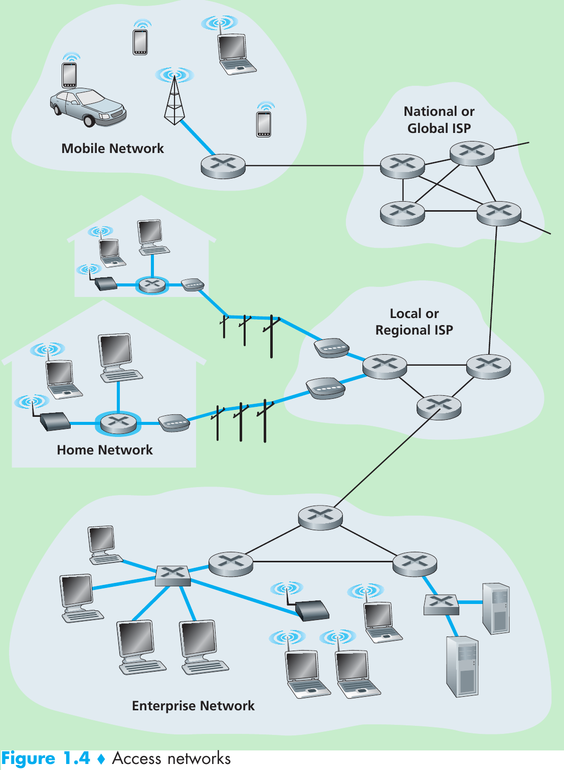
1.2.1 Access Networks
- Access network: the network that physically connects an end system to the first router (= “edge router”) on a path from the end system to any other distant end system.
Home Access: DSL, Cable, FTTH, Dial-Up, and Satellite - Two main types of broadband(宽带) residential access are digital subscriber line (DSL数字用户线路) and cable(电缆).
- A residence typically obtains DSL Internet access from the same local telephone company (telco) that provides its wired local phone access. When DSL is used, a customer’s telco is also its ISP.
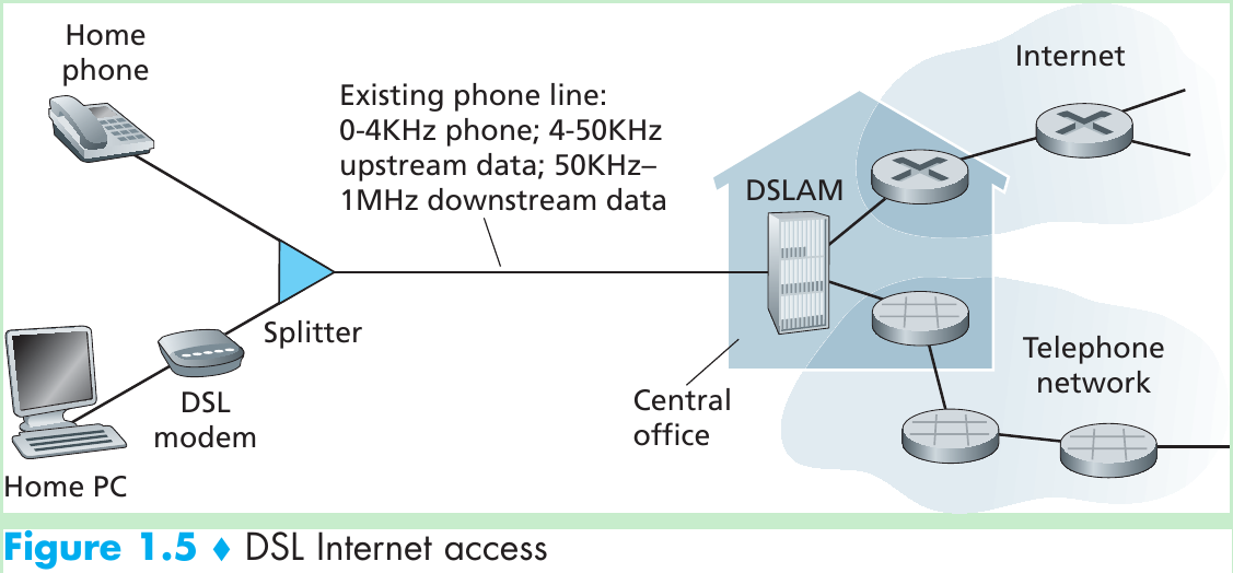
- Each customer’s DSL modem uses the existing telephone line (twisted-pair copper wire) to exchange data with a digital subscriber line access multiplexer (DSLAM) located in the telco’s local central office (CO). The home’s DSL modem takes digital data and translates it to high-frequency tones for transmission over telephone wires to the CO; the analog signals from many such houses are translated back into digital format at the DSLAM.
- The residential telephone line carries both data and traditional telephone signals simultaneously, which are encoded at different frequencies:
• A high-speed downstream channel, in the 50 kHz to 1 MHz band
• A medium-speed upstream channel, in the 4 kHz to 50 kHz band
• An ordinary two-way telephone channel, in the 0 to 4 kHz band - On the customer side, a splitter separates the data and telephone signals arriving to the home and forwards the data signal to the DSL modem. On the telco side, in the CO, the DSLAM separates the data and phone signals and sends the data into the Internet.
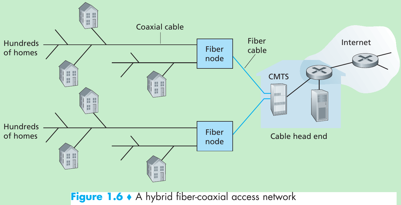
- A residence obtains cable Internet access from the same company that provides its cable television.
- Because both fiber(纤维) and coaxial cable(同轴电缆) are employed in this system, it is often referred to as hybrid fiber coax (HFC).
- Cable internet access requires cable modem which is typically an external device and connects to the home PC through an Ethernet port. At the cable head end, the cable modem termination system (CMTS) turning the analog signal sent from the cable modems in many downstream homes back into digital format.
- Cable Internet access is a shared broadcast medium(媒介). Every packet sent by the head end travels downstream on every link to every home and every packet sent by a home travels on the upstream channel to the head end. So if several users are simultaneously downloading a video file on the downstream channel, the actual rate at which each user receives its video file will be significantly lower than the aggregate cable downstream rate. Because the upstream channel is also shared, a distributed multiple access protocol is needed to coordinate transmissions and avoid collisions.
- Another technology that promises higher speeds is the deployment of fiber to the home(FTTH). The FTTH concept is providing an optical fiber path from the CO directly to the home.
- Technologies for optical(光学) distribution from the CO to the homes: The simplest optical distribution network is called direct fiber, with one fiber leaving the CO for each home. There are two competing optical-distribution network architectures that perform this splitting: active optical networks (AONs) and passive optical networks (PONs).
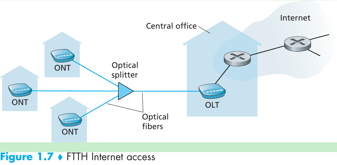
- FTTH using the PON distribution architecture. Each home has an optical network terminator (ONT), which is connected by optical fiber to a neighborhood splitter. The splitter combines a number of homes onto a single, shared optical fiber, which connects to an optical line terminator (OLT) in the telco’s CO. The OLT, providing conversion between optical and electrical signals, connects to the Internet via a telco router. In the home, users connect a home router to the ONT and access the Internet via this home router.
- In locations where DSL, cable, and FTTH are not available (e.g., in some rural settings), a satellite link can be used to connect a residence to the Internet at speeds of more than 1 Mbps.
- Dial-up access over traditional phone lines is based on the same model as DSL—a home modem connects over a phone line to a modem in the ISP. Dial-up access is very slow at 56 kbps.
- Local area network (LAN) is used to connect an end system to the edge router. Ethernet is the main access technology.
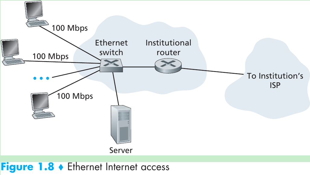
- Ethernet users use twisted-pair copper wire to connect to an Ethernet switch. The Ethernet switch is then in turn connected into the larger Internet.
- In a wireless LAN setting, wireless users transmit/receive packets to/from an access point that is connected into the wired Ethernet, which in turn is connected to the wired Internet.
1.2.2 Physical Media
- Physical media are divided into two categories: guided media and unguided media.
- Guided media: waves are guided along a solid medium. E.g.: fiber-optic cable, twisted-pair copper wire, coaxial cable.
- Unguided media: waves propagate in the atmosphere and in outer space. E.g.: wireless LAN, digital satellite channel.
1.3 The Network Core
1.3.1 Packet Switching
- In a network application, end systems exchange messages with each other. Messages can contain anything the application designer wants.
- To send a message from source to destination, the source breaks long messages into smaller chunks of data known as packets. Between source and destination, each packet travels through communication links and packet switches (two main types: routers and link-layer switches).
- Most packet switches use store-and-forward transmission at the inputs to the links, that is, the packet switch must receive the entire packet before it can begin to transmit the first bit of the packet onto the outbound link.
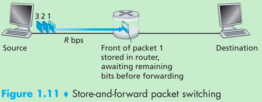
- In this figure, the source has three packets, each consisting of L bits, to send to the destination. The source has transmitted some of packet 1, and the front of packet 1 has already arrived at the router. The router cannot transmit the bits it has received; instead it must first buffer (i.e., “store”) the packet’s bits. Only after the router has received all of the packet’s bits can it begin to transmit (i.e., “forward”) the packet onto the outbound link.
- Calculate the amount of time that from when the source begins to send the first packet until the destination has received all three packets:
At time L/R, the router begins to forward the first packet. But also at time L/R the source will begin to send the second packet. Thus, at time 2L/R, the destination has received the first packet and the router has received the second packet. Similarly, at time 3L/R, the destination has received the first two packets and the router has received the third packet. Finally, at time 4L/R the destination has received all three packets! - Send one packet from source to destination over a path consisting of N links each of rate R (N-1 routers between source and destination).
d end-to-end = N * L / R - Each packet switch has multiple links attached to it. For each attached link, the packet switch has an output buffer (= output queue), which stores packets that the router is about to send into that link.
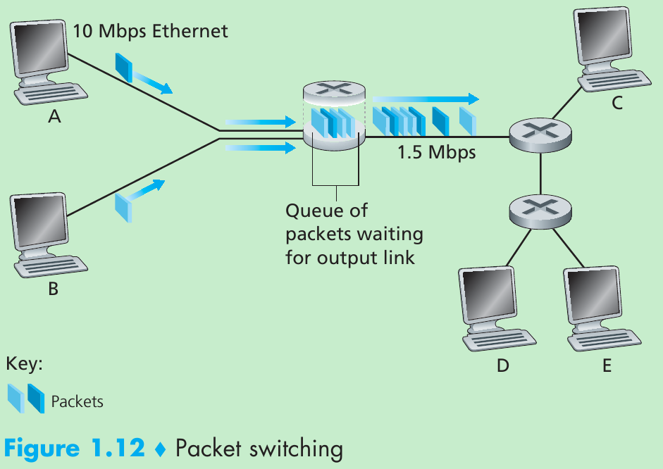
- If an arriving packet needs to be transmitted onto a link but finds the link busy with the transmission of another packet, the arriving packet must wait in the output buffer. Packets suffer output buffer queuing delays that are variable and depend on the level of congestion in the network. Since the amount of buffer space is finite, an arriving packet may find that the buffer is completely full with other packets waiting for transmission. In this case, packet loss will occur, either the arriving packet or one of the already-queued packets will be dropped.
- In the Internet, every end system has an address called an IP address. When a source end system wants to send a packet to a destination end system, the source includes the destination’s IP address in the packet’s header. This address has a hierarchical structure. Each router has a forwarding table that maps destination addresses (or portions of the destination addresses) to that router’s outbound links. When a packet arrives at a router, the router examines the address and searches its forwarding table, using this destination address, to find the appropriate outbound link. The router then directs the packet to this outbound link.
- Internet has a number of special routing protocols that are used to automatically set the forwarding tables. A routing protocol may determine the shortest path from each router to each destination and use the shortest path results to configure the forwarding tables in the routers.
1.3.2 Circuit Switching
- There are two fundamental approaches to moving data through a network of links and switches: circuit switching and packet switching.
- In circuit-switched networks, the resources needed along a path which provide communication between the end systems that are reserved for the duration of the communication session between the end systems.
In packet-switched networks, these resources are not reserved; a session’s messages use the resources on demand, and may have to wait (that is, queue) for access to a communication link. - Traditional telephone networks are examples of circuit-switched networks. When one person wants to send information to another over a telephone network. Before the sender can send the information, the network must establish a connection between the sender and the receiver. This connection is called a circuit. When the network establishes the circuit, it also reserves a constant transmission rate in the network’s links (a fraction of each link’s transmission capacity) for the duration of the connection.
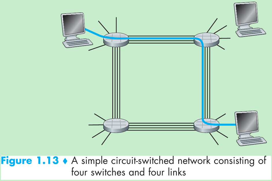
- In this example, the four circuit switches are interconnected by four links. Each of these links has four circuits, so that each link can support four simultaneous connections. The hosts are each directly connected to one of the switches. When two hosts want to communicate, the network establishes a dedicated end-to-end connection between the two hosts.
- In order for Host A to communicate with Host B, the network must first reserve one circuit on each of two links. In this example, the dedicated end-to-end connection uses the 2nd circuit in the first link and the 4th circuit in the second link. Because each link has four circuits, for each link used by the end-to-end connection, the connection gets one fourth of the link’s total transmission capacity for the duration of the connection.
- Packet-switched network: Different from circuit switching, the packet is sent into the network without reserving any link resources. If one of the links is congested because other packets need to be transmitted over the link at the same time, then the packet will have to wait in a buffer at the sending side of the transmission link and suffer a delay.
- A circuit in a link is implemented with either frequency-division multiplexing (FDM) or time-division multiplexing (TDM).
- With FDM, the frequency spectrum of a link is divided up among the connections established across the link. The link dedicates a frequency band to each connection for the duration of the connection. The width of the band is called the bandwidth.
- For a TDM link, time is divided into frames of fixed duration, and each frame is divided into a fixed number of time slots. When the network establishes a connection across a link, the network dedicates one time slot in every frame to this connection. These slots are dedicated for the sole use of that connection, with one time slot available for use (in every frame) to transmit the connection’s data.
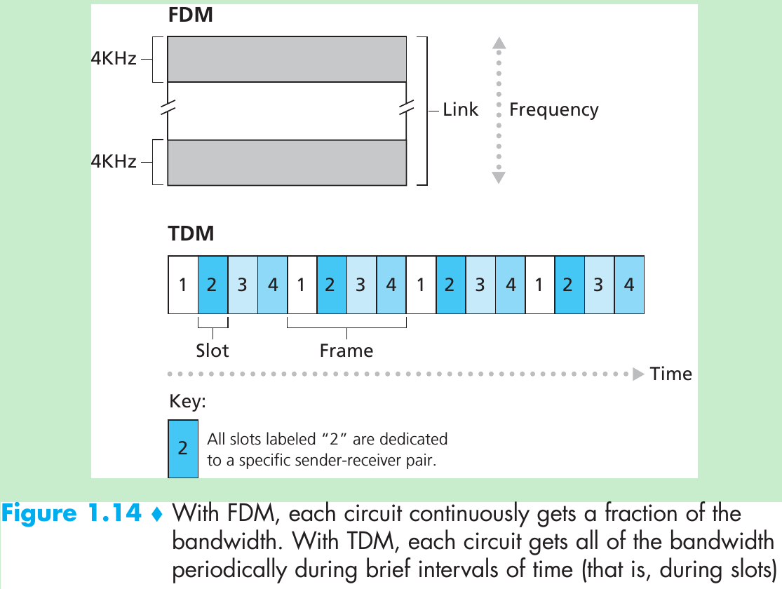
- Figure 1.14 illustrates FDM and TDM for a specific network link supporting up to four circuits. For FDM, the frequency domain is segmented into four bands, each of bandwidth 4 kHz. For TDM, the time domain is segmented into frames, with four time slots in each frame; each circuit is assigned the same dedicated slot in the revolving TDM frames. For TDM, the transmission rate of a circuit is equal to the frame rate multiplied by the number of bits in a slot. For example, if the link transmits 8,000 frames per second and each slot consists of 8 bits, then the transmission rate of a circuit is 64 kbps.
1.3.3 A Network of Networks
1.4 Delay, Loss, and Throughput in Packet-Switched Networks
1.4.1 Overview of Delay in Packet-Switched Networks
- When a packet travels from one node to the subsequent node along path, the packet suffers from several types of delays at each node along the path. nodal delay = processing delay + queuing delay + transmission delay + propagation delay.
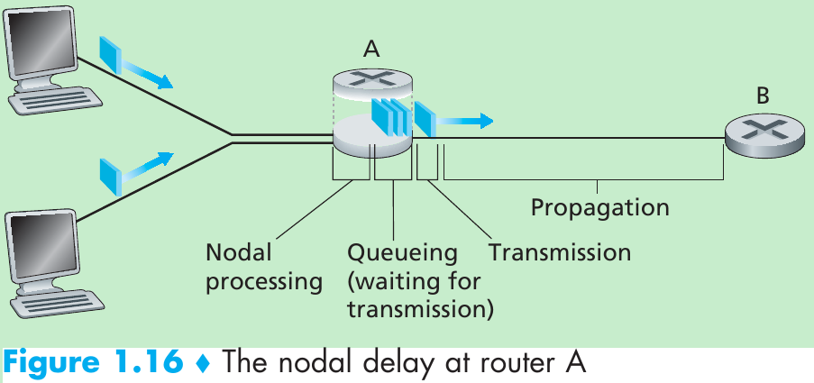
Processing delay(on the order of microseconds or less) - The time required to examine the packet’s header and determine where to direct the packet is part of the processing delay. The processing delay also include other factors, such as the time needed to check for bit-level errors in the packet that occurred in transmitting the packet’s bits from the upstream node to router A. After this nodal processing, the router directs the packet to the queue that precedes the link to B.
Queuing delay(on the order of microseconds to milliseconds) - The length of the queuing delay of a packet will depend on the number of earlier arriving packets that are queued and waiting for transmission onto the link.
Transmission delay(on the order of microseconds to milliseconds) - packet length = L bits; transmission rate = R bits/sec. The transmission delay = L/R.
Propagation Delay(on the order of milliseconds) - The time required to propagate from the beginning of the link to router B is the propagation delay. The bit propagates at speed of the link which depends on the physical medium and is equal to, or a little less than, the speed of light.
Differences between Transmission delay and Propagation Delay - The transmission delay is the amount of time required for the router to push out the packet; it is a function of the packet’s length and the transmission rate of the link, but has nothing to do with the distance between the two routers.
- The propagation delay is the time it takes a bit to propagate from one router to the next; it is a function of the distance between the two routers, but has nothing to do with the packet’s length or the transmission rate of the link.
1.4.2 Queuing Delay and Packet Loss
- Assume:
a: the average rate at which packets arrive at the queue (packets/sec).
R: transmission rate (bits/sec), at which bits are pushed out of the queue.
L: each packet’s size(bits)
The average rate at which bits arrive at the queue is L*a bits/sec; L*a/R is called the traffic intensity. - If L*a/R > 1, then the queuing delay occurs. Because the queue capacity is finite, a packet can arrive to find a full queue. With no place to store such a packet, a router will drop that packet.
1.4.3 End-to-End Delay
- Suppose there are N - 1 routers between the source host and the destination host. Let’s also suppose for the moment that the network is uncongested (so that queuing delays are negligible), the processing delay at each router and at the source host is d proc, the transmission rate out of each router and out of the source host is R bits/sec, and the propagation on each link is d prop. The nodal delays accumulate and give an end-to-end delay,
d end-end = N * (d proc + d trans + d prop)
where d trans = L/R (L is the packet size).
End System, Application, and Other Delays - In addition to processing, transmission, and propagation delays, there can be additional significant delays in the end systems. For example, an end system wanting to transmit a packet into a shared medium (e.g., as in a WiFi or cable modem scenario) may purposefully delay its transmission as part of its protocol for sharing the medium with other end systems(Chapter 5).
- Another important delay is media packetization delay, which is present in Voice-over-IP (VoIP) applications. In VoIP, the sending side must first fill a packet with encoded digitized speech before passing the packet to the Internet. This time to fill a packet—called the packetization delay—can be significant and can impact the user-perceived quality of a VoIP call.
1.4.4 Throughput in Computer Networks
- Consider transferring a large file from Host A to Host B across a computer network. The instantaneous throughput at any instant of time is the rate (in bits/sec) at which Host B is receiving the file. If the file consists of F bits and the transfer takes T seconds for Host B to receive all F bits, then the average throughput of the file transfer is F/T bits/sec.
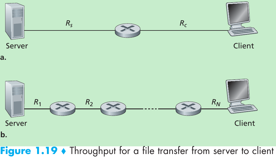
- Rs < Rc : throughput = Rs; Rs > Rc : throughput = Rc; for this simple two-link network, the throughput is min{Rs , Rc }. Throughput for a file transfer from server to client is min{R1, R2 ,…, RN}.
1.5 Protocol Layers and Their Service Models
1.5.1 Layered Architecture
Protocol Layering
- Each protocol belongs to one of the layers. A layer offers service to the layer above by (1) performing certain actions within that layer and by (2) using the services of the layer directly below it.
- A protocol layer can be implemented in software, in hardware, or in a combination of the two.
- Application-layer protocols(such as HTTP and SMTP) and transport-layer protocols are always implemented in software in the end systems.
- Network layer is often a mixed implementation of hardware and software.
- Physical layer and data link layers are implemented in hardware(network interface card, for example, Ethernet or WiFi interface cards) since they are responsible for handling communication over a specific link.
- Layering provides a structured way to discuss system components. Modularity makes it easier to update system components. One drawback of layering is that one layer may duplicate lower-layer functionality. For example, many protocol stacks provide error recovery on both a per-link basis and an end-to-end basis. A second potential drawback is that functionality at one layer may need information that is present only in another layer; this violates the goal of separation of layers.
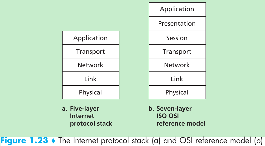
- When taken together, the protocols of the various layers are called the protocol stack. The Internet protocol stack consists of five layers: the physical, link, network, transport, and application layers.
Application Layer - The application layer is where network applications and their application-layer protocols reside. The Internet’s application layer includes many protocols, such as the HTTP, SMTP, and FTP. Certain network functions are done with the help of the domain name system (DNS).
- An application-layer protocol is distributed over multiple end systems, with the application in one end system using the protocol to exchange packets of information with the application in another end system. Packet of information at the application layer is a message.
Transport Layer - The Internet’s transport layer transports application-layer messages between application endpoints.
- There are two transport protocols, TCP and UDP, either of which can transport application-layer messages.
- TCP provides a connection-oriented service to its applications. This service includes guaranteed delivery of application-layer messages to the destination and flow control (that is, sender/receiver speed matching). TCP also breaks long messages into shorter segments and provides a congestion-control mechanism, so that a source throttles its transmission rate when the network is congested.
- The UDP protocol provides a connectionless service to its applications which provides no reliability, no flow control, and no congestion control.
- We refer to a transport-layer packet as a segment.
Network Layer - The Internet’s network layer is responsible for moving network-layer packets known as datagrams from one host to another. The Internet transport-layer protocol (TCP or UDP) in a source host passes a transport-layer segment and a destination address to the network layer. The network layer then provides the service of delivering the segment to the transport layer in the destination host.
- The Internet’s network layer includes the IP Protocol, which defines the fields in the datagram as well as how the end systems and routers act on these fields. There is only one IP protocol, and all Internet components that have a network layer must run the IP protocol.
- The Internet’s network layer also contains routing protocols that determine the routes that datagrams take between sources and destinations. The Internet has many routing protocols. Although the network layer contains both the IP protocol and numerous routing protocols, it is often simply referred to as the IP layer, reflecting the fact that IP is the glue that binds the Internet together.
Link Layer - To move a packet from one node to the next node in the route, the network layer relies on the services of the link layer. At each node, the network layer passes the datagram down to the link layer, which delivers the datagram to the next node along the route. At this next node, the link layer passes the datagram up to the network layer.
- The services provided by the link layer depend on the specific link-layer protocol that is employed over the link. For example, some link-layer protocols provide reliable delivery, from transmitting node to receiving node. Note that this reliable delivery service is different from the reliable delivery service of TCP, which provides reliable delivery from one end system to another. Examples of link-layer protocols include Ethernet, WiFi, and the cable access network’s DOCSIS protocol.
- A datagram may be handled by different link-layer protocols at different links along its route, so the network layer will receive a different service from each of the different link-layer protocols. We’ll refer to the link-layer packets as frames.
Physical Layer - Physical layer move the individual bits within the frame from one node to the next. The protocols in this layer are link dependent and further depend on the actual transmission medium of the link. In each case, a bit is moved across the link in a different way.
The OSI Model - The functionality of five of these layers is roughly the same as their similarly named Internet counterparts.
- The role of the presentation layer is to provide services that allow communicating applications to interpret the meaning of data exchanged. These services include data compression and data encryption and data description.
- The session layer provides for delimiting and synchronization of data exchange, including the means to build a checkpointing and recovery scheme.
1.5.2 Encapsulation
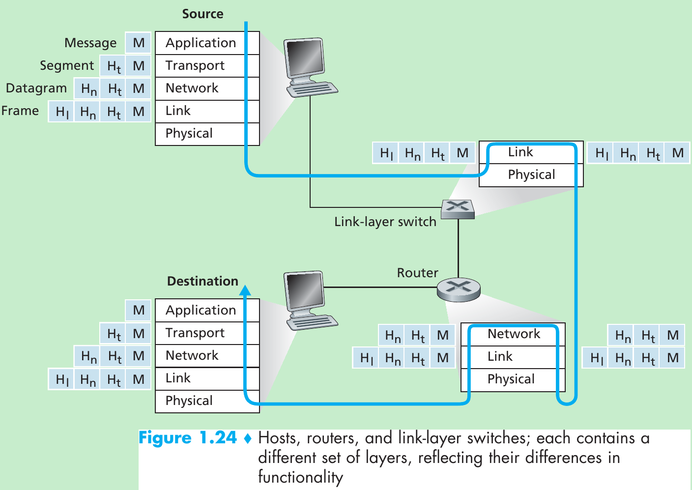
- Routers and link-layer switches are both packet switches and they organize their networking hardware and software into layers.
- Link-layer switches implement layers 1 and 2; routers implement layers 1 through 3. Internet routers are capable of implementing the IP protocol, while link-layer switches are not.
- At the sending host, an application-layer message (M) is passed to the transport layer. The transport layer takes the message and appends transport-layer header information Ht, that will be used by the receiver-side transport layer. The application-layer message and the transport-layer header information together constitute the transport-layer segment. The transport-layer segment thus encapsulates the application-layer message. The transport layer then passes the segment to the network layer, which adds network-layer header information (Hn) such as source and destination end system addresses, creating a network-layer datagram. The datagram is then passed to the link layer, which will add its own link-layer header information Hl and create a link-layer frame.
- At each layer, a packet has two types of fields: header fields and a payload field which is typically a packet from the layer above.
- List five tasks that a layer can perform. Is it possible that one (or more) of these tasks could be performed by two (or more) layers?
Five generic tasks are error control, flow control, segmentation and reassembly, multiplexing, and connection setup. These tasks can be duplicated at different layers. For example, error control is often provided at more than one layer. - Application-layer message: data which an application wants to send and passed onto the transport layer;
Transport-layer segment: generated by the transport layer and encapsulates application-layer message with transport layer header;
Network-layer datagram: encapsulates transport-layer segment with a network-layer header;
Link-layer frame: encapsulates network-layer datagram with a link-layer header.
1.6 Networks Under Attack
- Malware can spread in the form of a virus or a worm. Viruses are malware that require some form of user interaction to infect the user’s device. Worms are malware that can enter a device without any explicit user interaction.
- denial-of-service (DoS) attacks renders a network, host, or other piece of infrastructure unusable by normal users. Web servers, e-mail servers, DNS servers and institutional networks can all be subject to DoS attacks.
- Most Internet DoS attacks fall into one of three categories:
***Vulnerability attack. This involves sending a few well-crafted messages to a vulnerable application or operating system running on a targeted host. If the right sequence of packets is sent to a vulnerable application or operating system, the service can stop or, worse, the host can crash.
***Bandwidth flooding. The attacker sends a huge of packets to the targeted host—so many packets that the target’s access link becomes clogged, preventing legitimate packets from reaching the server.
***Connection flooding. The attacker establishes a large number of half-open or fully open TCP connections at the target host. The host can become so bogged down with these bogus connections that it stops accepting legitimate connections. - Place a passive receiver in the vicinity of the wireless transmitter, that receiver can obtain a copy of every packet that is transmitted. A passive receiver that records a copy of every packet that flies by is called a packet sniffer.
- The ability to inject packets into the Internet with a false source address is known as IP spoofing.
Please indicate the source: http://blog.csdn.net/gaoxiangnumber1
Welcome to my github: https://github.com/gaoxiangnumber1
0 0
- 1-Computer Networks and the Internet
- Answer to Computer Networks and Internet
- Computer and Communication Networks
- 电子书 computer and communication networks
- computer networks 笔记1
- computer networks outline (1)
- Networks of Innovation : Change and Meaning in the Age of the Internet
- Networks of Innovation: Change and Meaning in the Age of the Internet
- IPSec: The New Security Standard for the Internet, Intranets, and Virtual Private Networks
- Information Assurance: Security in the Information Environment (Computer Communications and Networks
- CSIT 561 Computer Networks: An Internet Perspective Homework1
- CSIT 561 Computer Networks: An Internet Perspective Homework2
- CSIT 561 Computer Networks: An Internet Perspective Homework3
- Analysis of Computer and Communication Networks
- Performance Analysis of Queuing and Computer Networks
- notes for the computer networks architechture
- [Computer Networks] Transport Layer, The Transport Service
- DELPHI AND THE INTERNET
- AndroidStudio下SVN的解除
- python编辑器
- 12款经典图片轮播jquery插件
- Android开发——程序锁的实现(可用于开发钓鱼登录界面)
- JSP概述
- 1-Computer Networks and the Internet
- windos下没有dirent,导致纯c应用非常得不爽,本文介绍一个在windows下使用dirent的方法
- linux菜鸟学习(七)----chmod,tar,chgrp,chown,gzip
- 抽象类、接口的具体用法
- phpstorm编辑远程项目
- 【JZOJ4648】锦标赛
- 【NOIP2016提高A组模拟7.15】计数
- Zenject——轻量级依赖注入框架 for Unity
- 详解C++中的纯虚函数(虚函数区别)&多态性 以及理解