20-TCP Bulk Data Flow
来源:互联网 发布:eos utility mac 编辑:程序博客网 时间:2024/06/06 05:12
Please indicate the source: http://blog.csdn.net/gaoxiangnumber1
Welcome to my github: https://github.com/gaoxiangnumber1
20.1 Introduction
20.2 Normal Data Flow
- Transfer 8192 bytes from svr4 to bsdi. We run sock on bsdi as server:
bsdi % sock -i -s 7777
-i and -s tell the program to run as a sink server(read from the network and discard the data) and the server’s port number is 7777. - The client is run as:
svr4 % sock -i -n8 bsdi 7777
This causes the client to perform eight 1024-byte writes to the network. - Figure 20.1 shows the time line for this exchange.
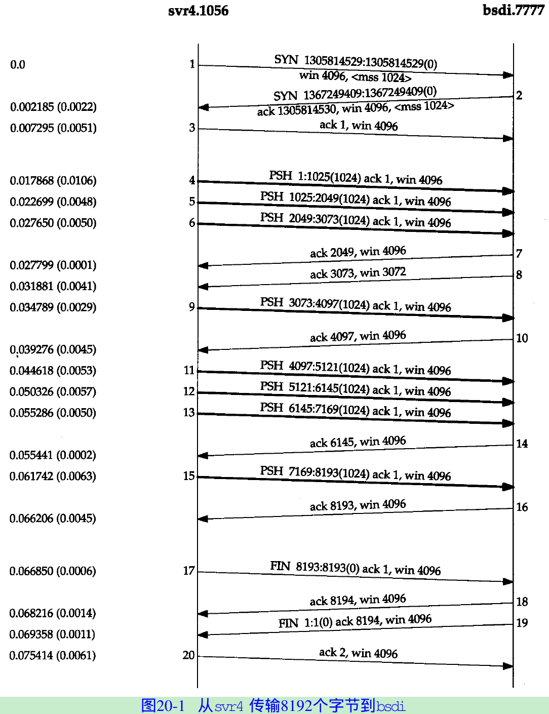
- When a packet arrives, it is processed by the device driver’s interrupt service routine and then placed onto IP’s input queue. IP will pass them to TCP in the same order as they arrived.
- When TCP processes segment 4, the connection is marked to generate a delayed ACK. TCP processes the next segment(5) and TCP now has two outstanding segments to ACK, the ACK of 2049 is generated(segment 7), and the delayed ACK flag for this connection is turned off.
- TCP processes the next input segment(6) and the connection is again marked for a delayed ACK. Before segment 9 arrives, it appears the delayed ACK timer goes off, and the ACK of 3073(segment 8) is generated. Segment 8 advertises a window of 3072 bytes, implying that there are still 1024 bytes of data in the TCP receive buffer that the application has not read.
- TCP’s sliding-window protocol: The ACKs are cumulative, they acknowledge that the receiver has correctly received all bytes up through the acknowledged sequence number minus one.
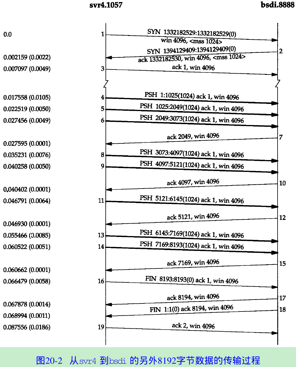
- Figure 20.2 shows another time line for the same exchange of data between the same two hosts, captured a few minutes after the one in Figure 20.1.
- The ACK of the final 1024 bytes of data appears in segment 17, along with the ACK of the FIN.
Fast Sender, Slow Receiver
- Figure 20.3 shows another time line from a fast sender to a slow receiver.
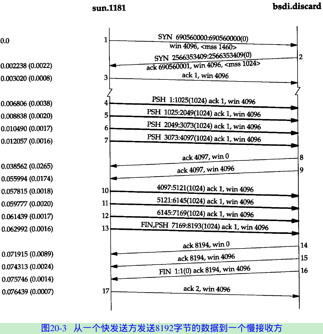
- The sender transmits four segments(4-7) to fill the receiver’s window. The sender then stops and waits for an ACK. The receiver sends the ACK(segment 8) with advertised window is 0 that means the receiver has all the data in TCP buffers.
- Another ACK(called a window update) is sent 17.4 ms later, announcing that the receiver can now receive another 4096 bytes.
- The sender transmits its final four segments(10-13) filling the receiver’s window. Segment 13 contains two flag bits: PUSH and FIN. This is followed by another two ACKs from the receiver that acknowledge the final 4096 bytes of data(bytes 4097 through 8192) and the FIN(numbered 8193).
20.3 Sliding Windows
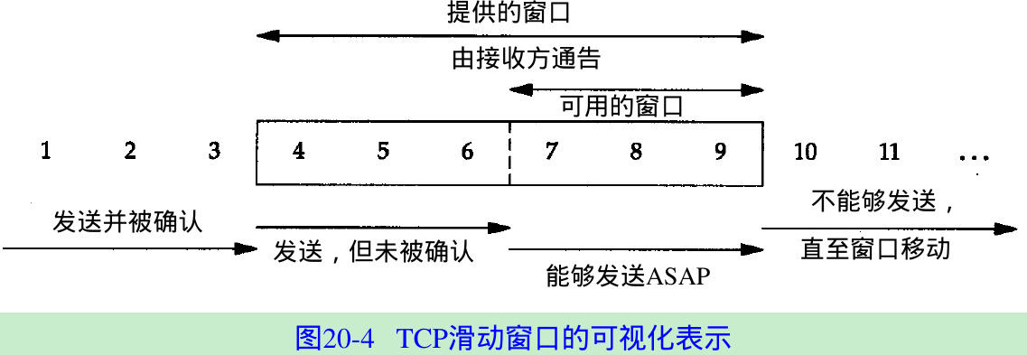
- Figure 20.4. The window advertised by the receiver is called the offered window and covers bytes 4 through 9, meaning that the receiver has acknowledged all bytes up through and including number 3, and has advertised a window size of 6.
- Over time this sliding window moves to the right, as the receiver acknowledges data. The relative motion of the two ends of the window increases or decreases the size of the window. Three terms describe the movement of the right and left edges of the window.
- The window closes as the left edge advances to the right. This happens when data is sent and acknowledged.
- The window opens when the right edge moves to the right, allowing more data to be sent. This happens when the receiving process reads acknowledged data, freeing up space in its TCP receive buffer.
- The window shrinks when the right edge moves to the left.
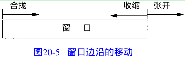
- Figure 20.5 shows these three terms.
- If an ACK were received that implied moving the left edge to the left, it is a duplicate ACK, and discarded.
- If the left edge reaches the right edge, it is called a zero window. This stops the sender from transmitting any data.
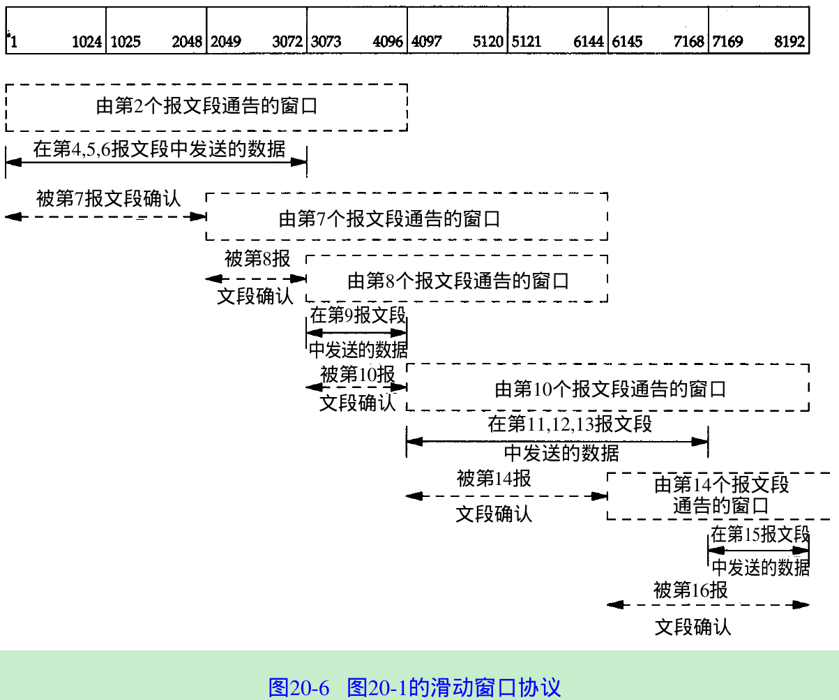
- Figure 20.6 shows the dynamics of TCP’s sliding window protocol for the data transfer in Figure 20.1.
The size of the window can decrease(from segment 7 to 8), but the right edge of the window must not move leftward.
20.4 Window Size
- The size of the window offered by the receiver can be controlled by the receiving process. The sockets API allows a process to set the sizes of the send buffer and the receive buffer. The size of the receive buffer is the maximum size of the advertised window for that connection. Some applications change the socket buffer sizes to increase performance.
- We can control the sizes of these buffers with sock.
bsdi % sock -i -a -R6144 5555
-R sets the size of the receive buffer to 6144 bytes. - We then start the client on sun and perform one write of 8192 bytes:
sun % sock -i -nl -w8192 bsdi 5555
Figure 20.7 shows the results.
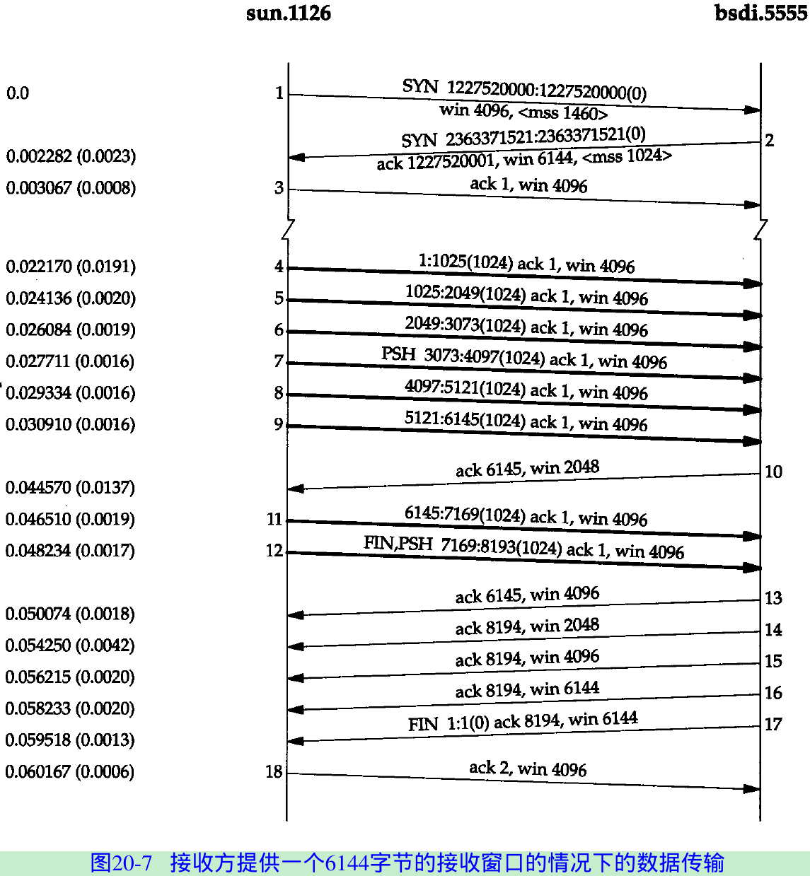
- Since the receiver’s window size is 6144 bytes in segment 2, the client sends six segments(segments 4-9) and stops.
Segment 10 acknowledges all the data(bytes 1 through 6144) but offers a window of 2048 because the receiving application hasn’t read more than 2048 bytes.
Segments 11 and 12 complete the data transfer from the client and the final data segment also carries the FIN flag.
Segment 13 contains the same acknowledgment sequence number as segment 10 with a larger window.
Segment 14 acknowledges the final 2048 bytes of data and the FIN.
Segments 15 and 16 just advertise a larger window.
Segments 17 and 18 complete the normal close.
20.5 PUSH Flag
- PUSH flag is a notification from the sender to the receiver for the receiver to pass all the data that it has to the receiving process. This data consists of whatever is in the segment with the PUSH flag, along with any other data the receiving TCP has collected for the receiving process.
- Berkeley-derived implementations automatically set the PUSH flag if the data in the segment being sent empties the send buffer. So, we see the PUSH flag set for each application write because data is usually sent when it’s written.
- Figure 20.1: PUSH flag turned on for all eight data segments because the client did eight writes of 1024 bytes and each write emptied the send buffer.
- Figure 20.7. PUSH flag was set on segment 7 because the size of the sender’s send buffer is 4096 bytes.
- Three consecutive ACKs(segments 14, 15, and 16): Many implementations send window update if the window increases by either two maximum sized segments(2048 = 1024(MSS) * 2) or 50% of the maximum possible window(2048 = 4096(maximum window) * 0.5).
- Figure 20.3.
- PUSH flag was on for the first four data segments(4-7) because each one caused a segment to be generated by TCP and passed to the IP layer. But then TCP had to stop, waiting for an ACK to move the 4096-byte window.
- While waiting for the ACK, TCP takes the final 4096 bytes of data from the application. When the window opens up(segment 9), the sending TCP knows it has four segments that it can send immediately, so it turns on the PUSH flag for the final segment(13).
20.6 Slow Start
- Slow start adds the congestion window to the sender’s TCP(called cwnd). When a new connection is established, the congestion window is initialized to one segment (i.e., the segment size announced by the other end). Each time an ACK is received, the congestion window is increased by one segment.
- The sender can transmit up to the minimum of the congestion window and the advertised window. The congestion window is flow control imposed by the sender, while the advertised window is flow control imposed by the receiver.
- The sender starts by transmitting one segment and waiting for its ACK. When that ACK is received, the congestion window is incremented from one to two, and two segments can be sent. When each of those two segments is acknowledged, the congestion window is increased to four.
- At some point the capacity of the internet can be reached, and an intermediate router will start discarding packets. This tells the sender that its congestion window has gotten too large.
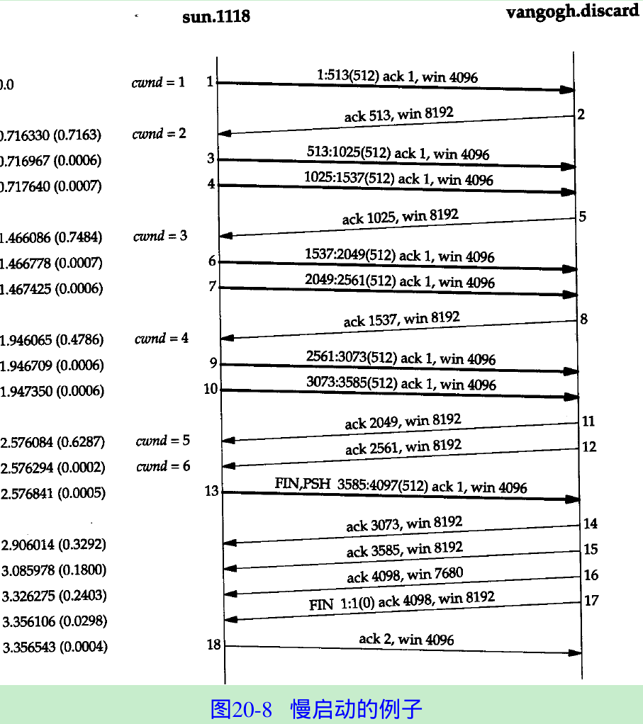
- Figure 20.8.
20.7 Bulk Data Throughput
- Figure 20.9 shows the steps of a connection. Segments carrying data going from the left to right are in the top half of each picture; ACKs go in the other direction in the bottom half of each picture.
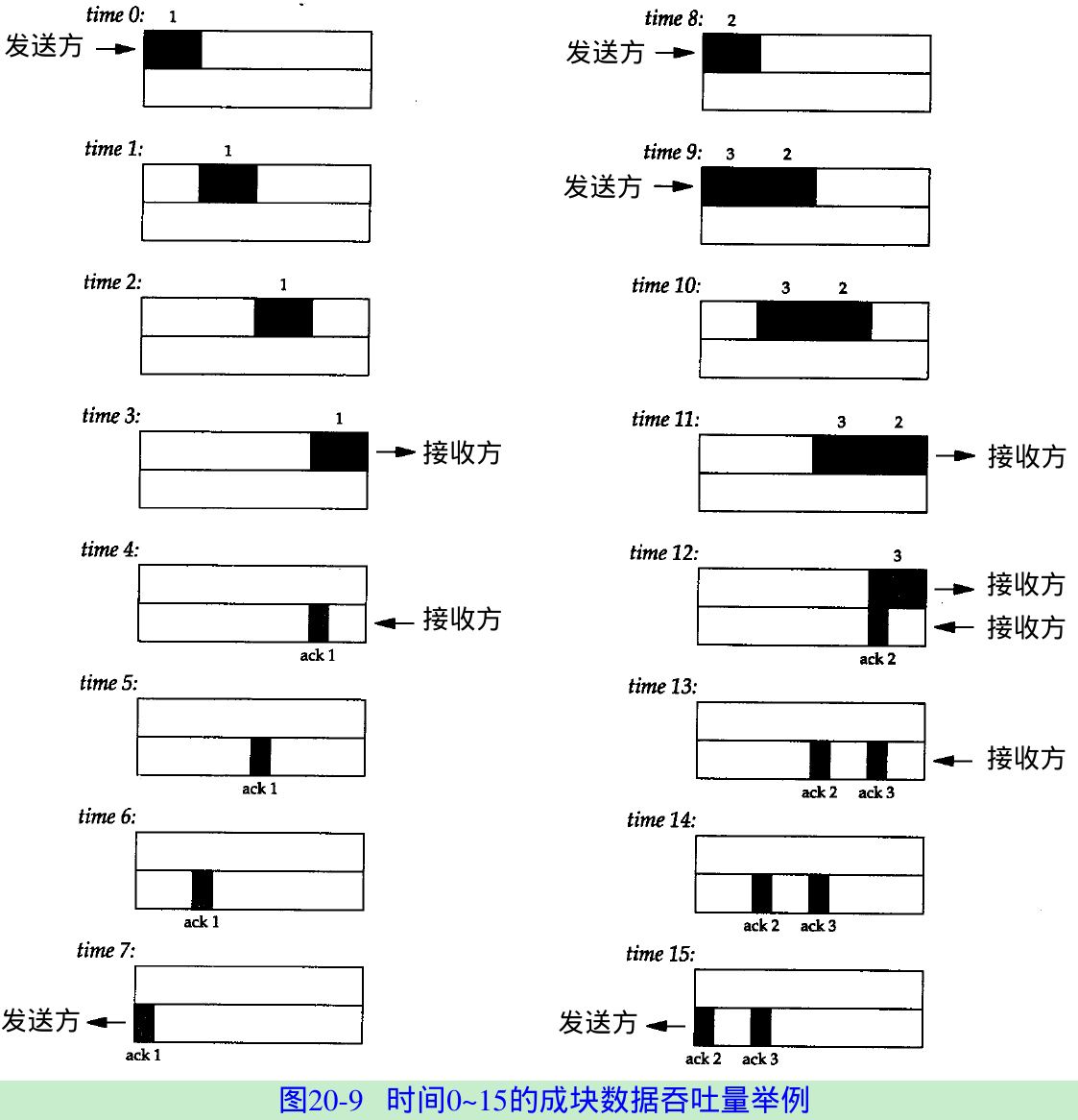
- T0: the sender transmits one segment. Since the sender is in slow start(congestion window is one segment), it must wait for the acknowledgment of this segment before continuing.
- T4: the receiver reads the segment and generates the acknowledgment.
- T5-7: the ACK moves back to the sender. Round-Trip Time(RTT) = 8 units of time.
- The time to send a packet depends on two factors: a propagation delay(light speed) and a transmission delay that depends on the speed of the media(how many bits per second the media can transmit).
For a given path between two nodes, the propagation delay is fixed, the transmission delay depends on the packet size. At lower speeds the transmission delay dominates, whereas at gigabit speeds the propagation delay dominates. - When the sender receives the ACK it can transmit two more segments(number 2 and 3) at times 8 and 9. Its congestion window is now two segments.
- These two segments ACKs are generated at times 12 and 13. The spacing of the ACKs returned to the sender is identical to the spacing of the data segments. This is called the self-clocking behavior of TCP.
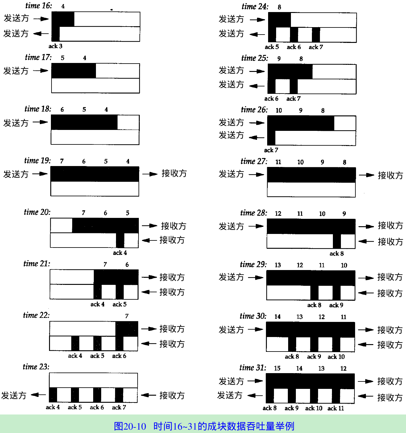
- Figure 20.10 shows the next 16 time units. The arrival of the two ACKs increases the congestion window from two to four segments, and these four segments are sent at times 16-19. The first of the ACKs returns at time 23. The four ACKs increase the congestion window from four to eight segments, and these eight segments are transmitted at times 24-31.
- At time 31 and at all successive times, the pipe between the sender and receiver is full. It cannot hold more data, regardless of the congestion window or the window advertised by the receiver. Each unit of time a segment is removed from the network by the receiver, and another is placed into the network by the sender.
Bandwidth-Delay Product
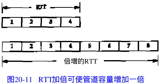
- How big should the window be? In our example, the sender needs to have eight segments outstanding and unacknowledged at any time, for maximum throughput. The receiver’s advertised window must be that large, since that limits how much the sender can transmit. We can calculate the capacity of the pipe as
capacity(bits) = bandwidth(bits/sec) * round-trip time(sec)
This is called the bandwidth-delay product. - Figure 20.11 shows how a doubling of the RTT-doubles the capacity of the pipe.
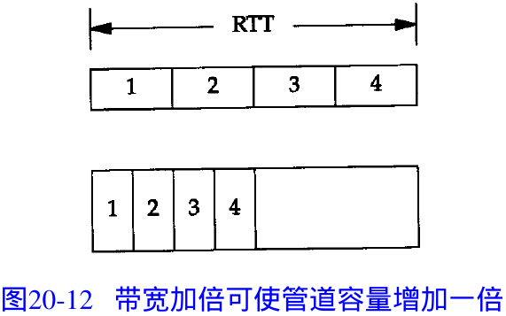
- Figure 20.12 shows doubling the bandwidth also doubles the capacity of the pipe.
Congestion
- Congestion can occur:
- When data arrives on a big pipe(a fast LAN) and gets sent out a smaller pipe(a slower WAN).
- When multiple input streams arrive at a router whose output capacity is less than the sum of the inputs.
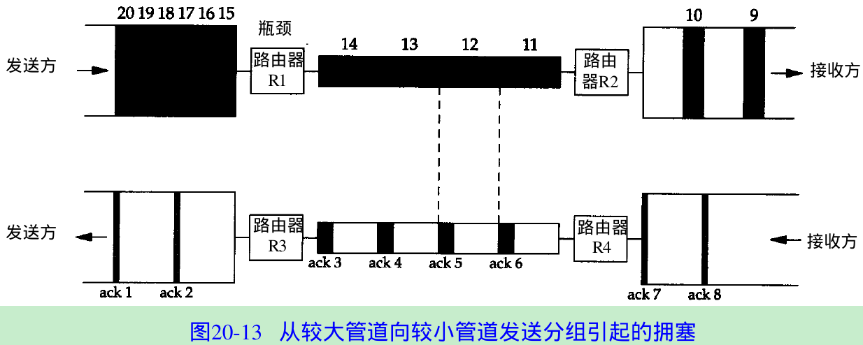
- Figure 20.13 shows a scenario with a big pipe feeding a smaller pipe.
Assume the sender did not use slow start and sent the segments 1-20 as fast as the LAN could take them. This assumes the receiving host advertised a window of at least 20 segments. The spaces of the ACKs correspond to the bandwidth of the slowest link. - The router R1 is the bottleneck because it is the congestion point. It can receive packets from the LAN on its left faster than they can be sent out the WAN on its right.
20.8 Urgent Mode
- TCP provides urgent mode that allowing one end to tell the other end that urgent data has been placed into the normal stream of data. After the other end is notified, it’s up to the receiving end to decide what to do.
- The notification of urgent data is setting two fields in the TCP header(Figure 17.2):
- URG bit is set.
- The 16-bit urgent pointer is set to an offset that must be added to the sequence number in the TCP header to obtain the sequence number of the last byte of urgent data.
- TCP must inform the receiving process when an urgent pointer is received and one was not already pending on the connection, or if the urgent pointer advances in the data stream.
Then the receiving application can read the data stream and must be able to tell when the urgent pointer is encountered. As long as data exists from the receiver’s current read position until the urgent pointer, the application is considered to be in urgent mode. After the urgent pointer is passed, the application returns to its normal mode. - No way to specify where the urgent data starts in the data stream. The only information sent by TCP is that urgent mode has begun(the URG bit) and the pointer to the last byte of urgent data. Everything else is left to the application.
- Urgent mode used in Telnet and Rlogin, when the interactive user types the interrupt key(Chapter 26); in FTP, when the interactive user aborts a file transfer(Chapter 27).
- Telnet and Rlogin use urgent mode from the server to the client because it’s possible for this direction of data flow to be stopped by the client TCP(i.e., it advertises a window of 0).
When the server enters urgent mode, the server TCP immediately sends the urgent pointer and the URG flag, even though it can’t send any data. When the client TCP receives this notification, it notifies the client process, so the client can read its input from the server, to open the window, and let the data flow. - If the sender enters urgent mode multiple times before the receiver processes all the data up through the first urgent pointer, then the urgent pointer advances in the data stream and its previous position at the receiver is lost. There is only one urgent pointer at the receiver and its value is overwritten when a new value for the urgent pointer arrives from the other end.
How TCP sends urgent data, even when the receiver’s window is closed?
- Start sock on bsdi and have it pause for 10 seconds(-P) after the connection is established, before it reads from the network. This lets the other end fill the send window.
bsdi % sock -i -s -P10 5555 - Then start the client on sun telling it to use a send buffer of 8192 bytes(-S) and perform six 1024-byte writes to the network(-n). Also specify -U5 telling it to write 1 byte of data and enter urgent mode before writing the fifth buffer to the network. We specify the verbose flag to see the order of the writes:
sun % sock -v -i -n6 -S8192 -U5 bsdi 5555connected on 140.252.13.33.1305 to 140.252.13.35.5555SO_SNDBUF = 8192TCP_MAXSEG = 1024wrote 1024 byteswrote 1024 byteswrote 1024 byteswrote 1024 byteswrote 1 byte of urgent datawrote 1024 byteswrote 1024 bytes- We set the send buffer size to 8192 bytes to let the sending application immediately write all its data. Figure 20.14 shows the tcpdump output for this exchange.
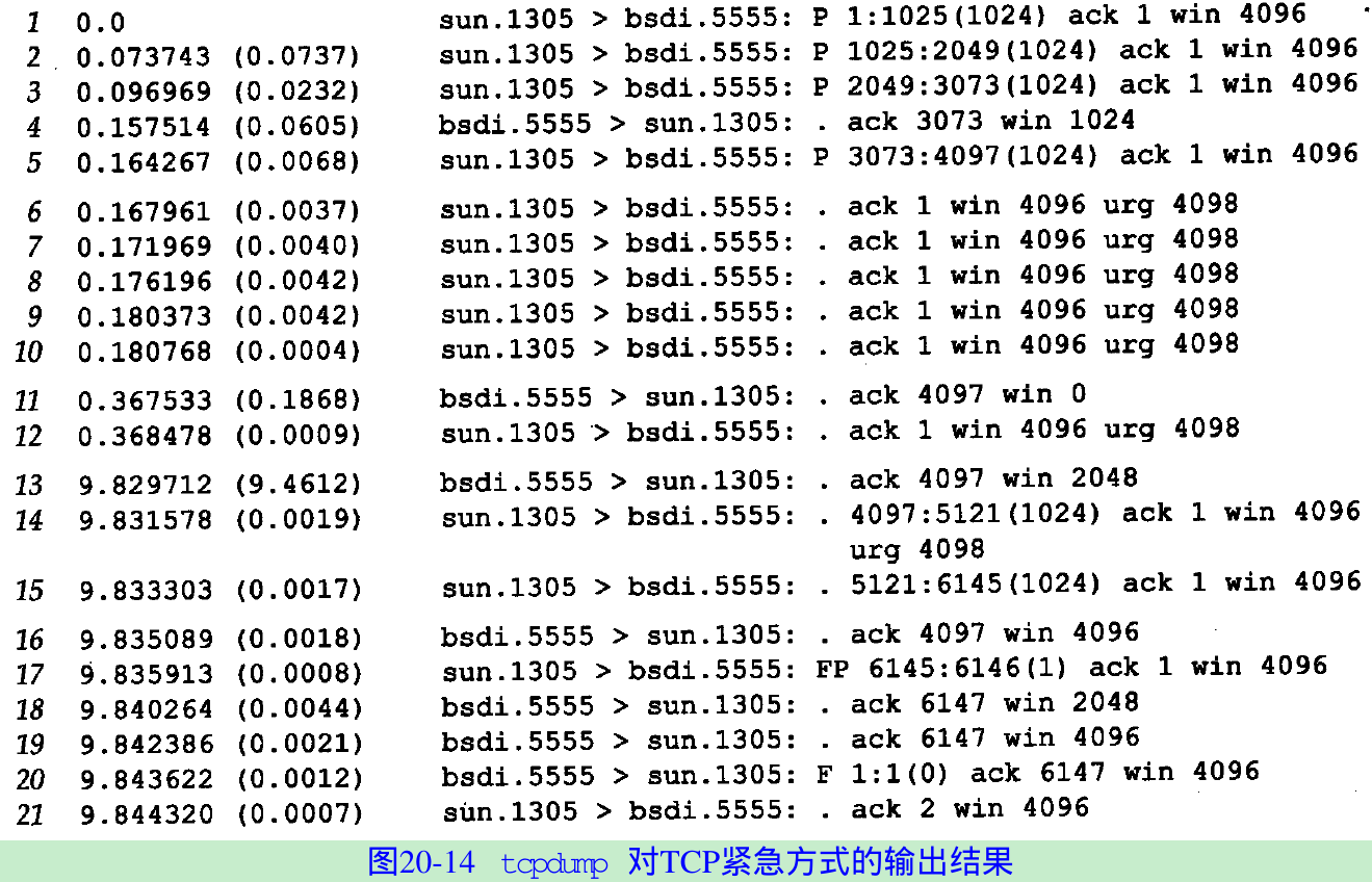
- Lines 1-5 show the sender filling the receiver’s window with four 1024-byte segments. The sender is then stopped because the receiver’s window is full. The ACK on line 4 acknowledges data, but does not move the right edge of the window.
- After the fourth write of normal data, the application writes 1 byte of data and enters urgent mode. The urgent pointer(4098) is sent with the URG flag even though the sender cannot send any data.
- Line 6-10: Five ACKs are sent in about 13 ms.
- The first is sent when the application writes 1 byte and enters urgent mode.
- The next two are sent when the application does the final two writes of 1024 bytes. Even though TCP can’t send these 2048 bytes, each time the application performs a write, the TCP output function is called, and when it sees that urgent mode has been entered, sends another urgent notification.
- The fourth ACK occurs when the application closes its end of the connection(TCP output function is again called). The sending application terminates milliseconds after it starts, before the receiving application has issued its first write. TCP queues all the data and sends it when it can. This is why we specified a send buffer size of 8192, so all data can fit in the buffer.
- The fifth ACK is generated by the reception of the ACK on line 4. The sending TCP has already queued its fourth segment for output(line 5) before this ACK arrives. The receipt of this ACK from the other end also causes the TCP output routine to be called.
- Line 11: The receiver acknowledges the final 1024 bytes of data with a window of 0.
- Line 12: The sender responds with a segment containing the urgent notification.
- Line 13: The receiver advertises a window of 2048 bytes when the application wakes up and reads data from the receive buffer.
- Line 14 and 15: The next two 1024-byte segments are sent. The first segment has the urgent notification set, since the urgent pointer is within this segment. The second segment has turned the urgent notification off.
- Line 16 and 17: When the receiver opens the window again, the sender transmits the final byte of data(6145) and initiates the normal connection termination.
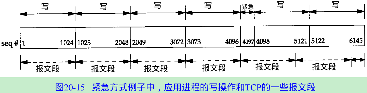
- Figure 20.15 shows the sequence numbers of the 6145 bytes of data that are sent. The sequence number of the byte written when urgent mode was entered is 4097, but the urgent pointer in Figure 20.14 is 4098 since SunOS sets the urgent pointer to 1 byte beyond the last byte of urgent data.
- TCP re-packet the data that the application wrote: The single byte that was output when urgent mode was entered is sent along with the next 1023 bytes of data in the buffer; the next segment contains 1024 bytes of data; the final segment contains 1 byte of data.
20.9 Summary
Exercise 20.1
In Figure 20.6 we could have shown a byte numbered 0 and a byte numbered 8193. What do these 2 bytes designate?
- Byte number 0 is SYN and byte number 8193 is FIN. SYN and FIN each occupy 1 byte in the sequence number space.
Exercise 20.2
Look ahead to Figure 22.1 and explain the setting of the PUSH flag by the host bsdi.

- The first application write causes the first segment to be sent with the PUSH flag. Since BSD uses slow start, it waits for the first ACK before sending any more data.
- During this time the next three application writes occur, and the sending TCP buffers the data to send. These three segments do not contain the PUSH flag since there is more data in the buffer to send.
- Eventually slow start catches up with the application writes and every application write causes a segment to be sent, and since that segment is the last one in the buffer, the PUSH flag is set.
Exercise 20.3
In a Usenet posting someone complained about a throughput of 120,000 bits/sec on a 256,000 bits/sec link with a 128-ms delay between the United States and Japan(47% utilization), and a throughput of 33,000 bits/sec when the link was routed over a satellite(13% utilization). What does the window size appear to be for both cases?(Assume a 500-ms delay for the satellite link.) How big should the window be for the satellite link?
- 120000/8*0.128 = 1920; 33000/8*0.5 = 2062.5
Solving the bandwidth-delay equation for the capacity, it is 1920 bytes for the first case, and 2062 for the satellite case. It appears that the receiving TCP is only advertising a window of 2,048 bytes. - A window greater than 16000(256000/8*0.5) bytes should be able to saturate the satellite link.
Exercise 20.4
If the API provided a way for a sending application to tell its TCP to turn on the PUSH flag, and a way for the receiver to tell if the PUSH flag was on in a received segment, could the flag then be used as a record marker?
- No, because TCP can repacketize data after a timeout(Section 21.11).
Exercise 20.5
In Figure 20.3 why aren’t segments 15 and 16 combined?
- Segment 15 is a window update sent automatically by the TCP module as a result of the application reading data, which causes the window to open(similar to segment 9).
- Segment 16 is a result of the application closing its end of the connection.
Exercise 20.6
In Figure 20.13 we assume that the ACKs come back nicely spaced, corresponding to the spacing of the data segments. What happens if the ACKs are queued somewhere on the return path, causing a bunch of them to arrive at the same time at the sender?
- This can cause the sender to inject packets into the network at a rate faster than the network can really handle, which is called ACK compression or ACK smashing [Mogul 1993, Sec. 15.8.13].
Please indicate the source: http://blog.csdn.net/gaoxiangnumber1
Welcome to my github: https://github.com/gaoxiangnumber1
- 20-TCP Bulk Data Flow
- tcp/ip学习笔记--第20章 TCP Bulk data flow
- TCP/IP 详解 卷1 ch20 TCP Bulk Data Flow
- 19-TCP Interactive Data Flow
- TCP/IP 详解 卷1 ch19 TCP Interactive Data Flow
- tcp/ip学习笔记--第19章 TCP interactive data flow (交互数据流)
- 3.5 Data Flow任务
- DS5000 Data flow
- loopback interface data flow
- Data Flow Diagrams (DFDs)
- Receiving Module Data Flow
- UVa10594 Data Flow
- uva 10594Data Flow
- llvm:Data Flow Graph
- Spring Cloud Data Flow
- Spring Data Flow
- Interface, Data Structure & Flow Chart
- SSIS Custom Data Flow Task
- Servlet容器Tomcat中web.xml中url-pattern的配置详解[附带源码分析]
- React Native环境搭建 (android/mac环境)
- C语言循环链表的实现与操作
- IntelliJ IDEA 主题、字体、编辑区主题、文件编码修改
- 监听软键盘 刷新布局视图
- 20-TCP Bulk Data Flow
- Windows下搭建git服务器
- 浮点数与零比较
- SpannableString与SpannableStringBuilder使用
- C# 如何求两个日期之间的时间
- 1-解析命令行参数-ParseArguments
- 附录
- 知识管理软件之三 代码助手
- Makefile简单使用的例子