Lesson 11: 绘制三角形
来源:互联网 发布:java编辑工具 编辑:程序博客网 时间:2024/06/08 04:21
原文地址:
http://www.directxtutorial.com/Lesson.aspx?lessonid=11-4-5
一个三角形由三个点组成,也可以叫做顶点。用一个顶点数组来定义一个三角形,为了GPU能够渲染这个三角形,我们必须告诉GPU三角形的三个顶点的坐标。
顶点缓存:
在Direct3D 11中,向顶点信息(如坐标)叫保存在一个缓冲区资源内。如果一个缓冲区用来存放顶点信息,那么它就叫做顶点缓冲区。我们必须创建一个足够大的顶点缓冲区来保存者三个顶点坐标。在Direct3D 11中,创建一个顶点缓冲区必须指定大小(以byte为单位)。我们知道这个缓冲区有足够的空间来存放这个顶点,但是每个顶点有多少byte呢?回答好这个问题之前,我们需要知道顶点格式。
一个顶点有一个坐标信息。但通常不仅仅只有顶点信息,它也可能有其他的属性。比如:向量,多个的颜色,纹理坐标等等。顶点格式将定义这些属性在内存中如何存放:每个数据属性的用法,每个数据属性的大小,还有属性之间的排列。由于属性通常有不同的类型,类似于C中的结构体,一个顶点通常用一个结构体表示。可以方便地根据一个结构体的大小来获取顶点的大小。
struct VERTEX{ FLOAT X, Y, Z; // position D3DXCOLOR Color; // color};现在我们有一个结构体来表示我们的顶点。在应用程序中要保存好这些顶点信息。然而,当我们需要GPU渲染包含这些顶点的顶点缓冲区的时候,我们要将它填入一个内存块中。GPU也必须知道顶点格式,以便于从缓冲区中提取顶点信息。完成这个需要了解input layout。
Input Layout:
在Direct3D 11中,Input Layout是Direct3D对象,它能以一种GPU能够理解的方式来描述顶点结构体。每个顶点属性能够用D3D11_INPUT_ELEMENT_DESC结构体来描述。一个应用程序定义一个或多个的D3D11_INPUT_ELEMENT_DESC 结构体数组。使用这些数组来创建Input Layout对象来描述顶点。
D3D11_INPUT_ELEMENT_DESC结构体细节如下:
typedef struct D3D11_INPUT_ELEMENT_DESC { LPCSTR SemanticName; UINT SemanticIndex; DXGI_FORMAT Format; UINT InputSlot; UINT AlignedByteOffset; D3D11_INPUT_CLASSIFICATION InputSlotClass; UINT InstanceDataStepRate; } D3D11_INPUT_ELEMENT_DESC;Semantic Name是一个用来描述属性的字符串。这个字符串表示一个单词,这个单词可以使用C能够定义的任何格式。比如用于描述顶点坐标可以使用“POSITION”字符串。
Semantic Index,这个用来描述索引,当SemanticName相同的情况下就可以使用索引来描述到底哪个才是当前需要的。因为一个顶点可能包含多个颜色,或纹理坐标等等,例如多个颜色可以使用如COLOR0,COLOR1来描述,也可以都是用COLOR来描述,使用0和1来填充SemanticIndex。
Format描述这个数据的数据类型。目前,DXGI_FORMAT_R32G32B32_FLOAT数据格式有3个32位的浮点数,使这个元素有12字节大小。DXGI_FORMAT_R16G16B16A16_UINT有4个16字节无符号整型数,使这个元素8字节大小。
InputSlot,输入槽,在前面提到过的,每一个顶点信息都通过一个Vertex Buffer输入让GPU识别,在Direct 3D 11中多个顶点信息可以同时的输入,最多可以有16个,这样就需要让GPU知道当前将使用哪个Vertex Buffer信息,也就是这个值将在0到15之间了。
AlignedByteOffset,内存偏移量,告诉GPU当前缓存内存起始偏移量。
InputSlotClass,这个一般使用D3D11_INPUT_PER_VERTEX_DATA来填充,当使用实例数据类型时,将使用D3D11_INPUT_PER_INSTANCE_DATA,这个是比较高级的或许在我们以后的学习当中会遇到,这里我们不大清楚,就先放过。
InstanceDataStepRate, 这个用于Instancing,既然我们没有使用Instancing,InstanceDataStepRate没有被用到,所以必须设置为0。
现在我们能够定义我们的D3D11_INPUT_ELEMENT_DESC数组并且创建input layout:
D3D11_INPUT_ELEMENT_DESC ied[] ={ {"POSITION", 0, DXGI_FORMAT_R32G32B32_FLOAT, 0, 0, D3D11_INPUT_PER_VERTEX_DATA, 0}, {"COLOR", 0, DXGI_FORMAT_R32G32B32A32_FLOAT, 0, 12, D3D11_INPUT_PER_VERTEX_DATA, 0},};接下来通过ID3D11Device::CreateInputLayout()方法来创建我们的Vertex Layout对象。
函数原型如下:
HRESULT CreateInputLayout( D3D11_INPUT_ELEMENT_DESC *pInputElementDescs, UINT NumElements, void *pShaderBytecodeWithInputSignature, SIZE_T BytecodeLength, ID3D11InputLayout **pInputLayout);D3D11_INPUT_ELEMENT_DESC *pInputElementDescs,
输入元素描述数组的指针,例如这里我们是ied数组,传入的是它的地址。
UINT NumElements,
这个数组里元素的数量,这里是2。
void *pShaderBytecodeWithInputSignature,
流水线中第一个着色器的指针,也就是顶点着色器。我们通过调用GetBufferPointer()函数来获得。
SIZE_T BytecodeLength,
着色器文件的字节长度,我们通过调用GetBufferSize()函数来获得。
ID3D11InputLayout **pInputLayout
Input Layout的COM接口指针。
最后,我们完成创建之后,需要调用IASetInputLayout()函数对它进行激活,唯一参数是Input Layout接口。
所以整个初始化流水线函数修改如下:
void InitPipeline(){ // load and compile the two shaders ID3D10Blob *VS, *PS; D3DX11CompileFromFile(L"shaders.shader", 0, 0, "VShader", "vs_4_0", 0, 0, 0, &VS, 0, 0); D3DX11CompileFromFile(L"shaders.shader", 0, 0, "PShader", "ps_4_0", 0, 0, 0, &PS, 0, 0); // encapsulate both shaders into shader objects dev->CreateVertexShader(VS->GetBufferPointer(), VS->GetBufferSize(), NULL, &pVS); dev->CreatePixelShader(PS->GetBufferPointer(), PS->GetBufferSize(), NULL, &pPS); // set the shader objects devcon->VSSetShader(pVS, 0, 0); devcon->PSSetShader(pPS, 0, 0); // create the input layout object D3D11_INPUT_ELEMENT_DESC ied[] = { {"POSITION", 0, DXGI_FORMAT_R32G32B32_FLOAT, 0, 0, D3D11_INPUT_PER_VERTEX_DATA, 0}, {"COLOR", 0, DXGI_FORMAT_R32G32B32A32_FLOAT, 0, 12, D3D11_INPUT_PER_VERTEX_DATA, 0}, }; dev->CreateInputLayout(ied, 2, VS->GetBufferPointer(), VS->GetBufferSize(), &pLayout); devcon->IASetInputLayout(pLayout);}创建顶点缓存:
知道了上面的内容我们还需要做一件事,在初始化时我们必须创建一个Vertex Buffer并且承载了这个顶点的数据信息。
为了创建Vertex Buffer,必须填充两个结构D3D11_BUFFER_DESC和D3D11_SUBRESOURCE_DATA,然后使用ID3D11Device::CreateBuffer()方法进行创建。
D3D11_BUFFER_DESC结构对Vertex Buffer要创建的内容对象进行描述,而D3D11_SUBRESOURCE_DATA则是包含了具体的数据信息,这些数据信息在创建时会进行拷贝。创建缓存和初始化是在同一时间完成的,在创建后我们可以使用ID3D11DeviceContext::IASetVertexBuffers()方法将其绑定到设备中,那样我们就可以在屏幕上呈现出来了。
Vertex Buffer in Video Memory When Needed 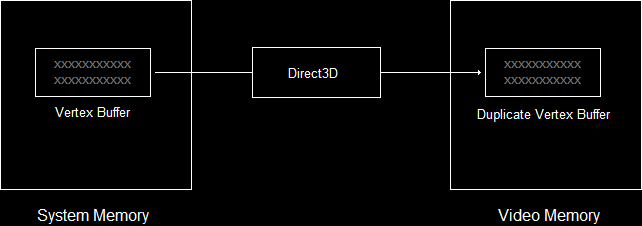
填充D3D11_BUFFER_DESC结构体:
ID3D11Buffer *pVBuffer; // globalD3D11_BUFFER_DESC bd;ZeroMemory(&bd, sizeof(bd));bd.Usage = D3D11_USAGE_DYNAMIC; // write access access by CPU and GPUbd.ByteWidth = sizeof(VERTEX) * 3; // size is the VERTEX struct * 3bd.BindFlags = D3D11_BIND_VERTEX_BUFFER; // use as a vertex bufferbd.CPUAccessFlags = D3D11_CPU_ACCESS_WRITE; // allow CPU to write in bufferdev->CreateBuffer(&bd, NULL, &pVBuffer); // create the bufferbd.Usage:
为了有效地设置缓存,Direct3D必须知道我们对CPU和GPU的使用权。
可有以下参数选择:

bd.ByteWidth:
创建的缓冲区的大小。
bd.BindFlags:
绑定标识,用于告诉Direct3D我们打算使用的缓冲区种类。
bd.CPUAccessFlags:
CPU使用权标识,可选D3D11_CPU_ACCESS_WRITE 和D3D11_CPU_ACCESS_READ。这里我们需要在系统内存中拷贝数据到缓冲区中,所以我们选用前者。
dev->CreateBuffer(&bd, NULL, &pVBuffer);
通过设备调用CreateBuffer()函数完成缓冲区的创建。
第一个参数是描述结构体的地址。
第二个参数用于使用特定格式来初始化内存。
第三个参数是缓冲区对象的地址。
通过映射来填充顶点缓存:
Map是CPU和GPU沟通的桥梁。
D3D11_MAPPED_SUBRESOURCE ms;devcon->Map(pVBuffer, NULL, D3D11_MAP_WRITE_DISCARD, NULL, &ms); // map the buffermemcpy(ms.pData, OurVertices, sizeof(OurVertices)); // copy the datadevcon->Unmap(pVBuffer, NULL); // unmap the bufferD3D11_MAPPED_SUBRESOURCE ms;
这个结构体用于返回描述填充缓冲区的信息。
这个结构体原型:
typedef struct D3D11_MAPPED_SUBRESOURCE { void *pData; UINT RowPitch; UINT DepthPitch; } D3D11_MAPPED_SUBRESOURCE;devcon->Map()
第一个参数是缓冲区的地址。
第二个参数,UINT Subresource。暂且设为NULL。
第三个参数,当映射时我们允许CPU控制的使用权。可有下列参数选择: 
第四个参数是一个标识,在NULL或者D3D11_MAP_FLAG_DO_NOT_WAIT中进行选择。它强制程序运行,即使是GPU仍在对缓冲区进行工作中。
第五个参数是D3D11_MAPPED_SUBRESOURCE结构体的地址,它将返回我们所需要的信息。
memcpy()
复制所需要的信息
ms.pData作为目标,OurVertices作为内容,以及sizeof(OurVertices)作为大小
devcon->Unmap()
解映射,使得GPU重新获取对该resouce的读写权。
第一个参数是缓冲区。
第二个参数是UINT Subresource。
设置顶点缓存:
IASetVertexBuffers函数原型如下:
void IASetVertexBuffers(UINT StartSlot, UINT NumBuffers, ID3D11Buffer **ppVertexBuffers, UINT *pStrides, UINT *pOffsets);第一个参数是要进行绑定的buff 索引, 因为 buffer 会有很多个, 这里需要进行指定。
第二个参数是指上述的 buffer 个数;
第三个参数就是存储这些buffer的地方;
第四个参数是指向步值数组的指针。每个步值就是顶点缓存中被使用的元素的大小(用字节表示)。
第五个参数是指向偏移值数组的指针。每个偏移值就是顶点缓存中第一个元素和第一个被使用的元素之间的字节数。
这个函数就像这样解释:
UINT stride = sizeof(VERTEX);UINT offset = 0;devcon->IASetVertexBuffers(0, 1, &pBuffer, &stride, &offset);IAsetPrimitiveTopology():
这个函数仅仅有一个参数,用于告诉 Direct3D 采用哪种方式渲染几何体。
可用方式有如下:

它在设备上下文中进行调用: devcon->IASetPrimitiveTopology(D3D11_PRIMITIVE_TOPOLOGY_TRIANGLELIST);
接下来,就在后台缓冲区中进行绘制:
//通过设备上下文调用Draw()函数devcon->Draw(3, 0); // draw 3 vertices, starting from vertex 0函数原型如下:
void Draw(UINT VertexCount, // the number of vertices to be drawn UINT StartVertexLocation); // the first vertex to be drawn我们知道,整个绘制工作是在渲染框架中完成的,所以这个函数修改如下:
// this is the function used to render a single framevoid RenderFrame(void){ // clear the back buffer to a deep blue devcon->ClearRenderTargetView(backbuffer, D3DXCOLOR(0.0f, 0.2f, 0.4f, 1.0f)); // select which vertex buffer to display UINT stride = sizeof(VERTEX); UINT offset = 0; devcon->IASetVertexBuffers(0, 1, &pVBuffer, &stride, &offset); // select which primtive type we are using devcon->IASetPrimitiveTopology(D3D10_PRIMITIVE_TOPOLOGY_TRIANGLELIST); // draw the vertex buffer to the back buffer devcon->Draw(3, 0); // switch the back buffer and the front buffer swapchain->Present(0, 0);}整个流程快速复习:
1.使用着色器:
- Loaded and compiled the two shaders
- Created objects for each one.
- Set the two objects.
2.顶点缓存:
- Created three vertices with both position and color.
- Created a vertex buffer object.
- Copied the vertices into the vertex buffer by mapping it, copying the data, and unmapping it.
3.验证Input Layout:
- Created input element descriptions for the position and the color.
- Created an input layout object using the shader information.
- Set the input layout object.
4.简单绘制:
- Set which vertex buffer to use (there was only one to choose from).
- Set which primitive type to use.
- Draw the triangle.
完整代码:
main.cpp:
// include the basic windows header files and the Direct3D header files#include <windows.h>#include <windowsx.h>#include <d3d11.h>#include <d3dx11.h>#include <d3dx10.h>// include the Direct3D Library file#pragma comment (lib, "d3d11.lib")#pragma comment (lib, "d3dx11.lib")#pragma comment (lib, "d3dx10.lib")// define the screen resolution#define SCREEN_WIDTH 800#define SCREEN_HEIGHT 600// global declarationsIDXGISwapChain *swapchain; // the pointer to the swap chain interfaceID3D11Device *dev; // the pointer to our Direct3D device interfaceID3D11DeviceContext *devcon; // the pointer to our Direct3D device contextID3D11RenderTargetView *backbuffer; // the pointer to our back bufferID3D11InputLayout *pLayout; // the pointer to the input layoutID3D11VertexShader *pVS; // the pointer to the vertex shaderID3D11PixelShader *pPS; // the pointer to the pixel shaderID3D11Buffer *pVBuffer; // the pointer to the vertex buffer// a struct to define a single vertexstruct VERTEX{FLOAT X, Y, Z; D3DXCOLOR Color;};// function prototypesvoid InitD3D(HWND hWnd); // sets up and initializes Direct3Dvoid RenderFrame(void); // renders a single framevoid CleanD3D(void); // closes Direct3D and releases memoryvoid InitGraphics(void); // creates the shape to rendervoid InitPipeline(void); // loads and prepares the shaders// the WindowProc function prototypeLRESULT CALLBACK WindowProc(HWND hWnd, UINT message, WPARAM wParam, LPARAM lParam);// the entry point for any Windows programint WINAPI WinMain(HINSTANCE hInstance, HINSTANCE hPrevInstance, LPSTR lpCmdLine, int nCmdShow){ HWND hWnd; WNDCLASSEX wc; ZeroMemory(&wc, sizeof(WNDCLASSEX)); wc.cbSize = sizeof(WNDCLASSEX); wc.style = CS_HREDRAW | CS_VREDRAW; wc.lpfnWndProc = WindowProc; wc.hInstance = hInstance; wc.hCursor = LoadCursor(NULL, IDC_ARROW); wc.lpszClassName = L"WindowClass"; RegisterClassEx(&wc); RECT wr = {0, 0, SCREEN_WIDTH, SCREEN_HEIGHT}; AdjustWindowRect(&wr, WS_OVERLAPPEDWINDOW, FALSE); hWnd = CreateWindowEx(NULL, L"WindowClass", L"Our First Direct3D Program", WS_OVERLAPPEDWINDOW, 300, 300, wr.right - wr.left, wr.bottom - wr.top, NULL, NULL, hInstance, NULL); ShowWindow(hWnd, nCmdShow); // set up and initialize Direct3D InitD3D(hWnd); // enter the main loop: MSG msg; while(TRUE) { if(PeekMessage(&msg, NULL, 0, 0, PM_REMOVE)) { TranslateMessage(&msg); DispatchMessage(&msg); if(msg.message == WM_QUIT) break; } RenderFrame(); } // clean up DirectX and COM CleanD3D(); return msg.wParam;}// this is the main message handler for the programLRESULT CALLBACK WindowProc(HWND hWnd, UINT message, WPARAM wParam, LPARAM lParam){ switch(message) { case WM_DESTROY: { PostQuitMessage(0); return 0; } break; } return DefWindowProc (hWnd, message, wParam, lParam);}// this function initializes and prepares Direct3D for usevoid InitD3D(HWND hWnd){ // create a struct to hold information about the swap chain DXGI_SWAP_CHAIN_DESC scd; // clear out the struct for use ZeroMemory(&scd, sizeof(DXGI_SWAP_CHAIN_DESC)); // fill the swap chain description struct scd.BufferCount = 1; // one back buffer scd.BufferDesc.Format = DXGI_FORMAT_R8G8B8A8_UNORM; // use 32-bit color scd.BufferDesc.Width = SCREEN_WIDTH; // set the back buffer width scd.BufferDesc.Height = SCREEN_HEIGHT; // set the back buffer height scd.BufferUsage = DXGI_USAGE_RENDER_TARGET_OUTPUT; // how swap chain is to be used scd.OutputWindow = hWnd; // the window to be used scd.SampleDesc.Count = 4; // how many multisamples scd.Windowed = TRUE; // windowed/full-screen mode scd.Flags = DXGI_SWAP_CHAIN_FLAG_ALLOW_MODE_SWITCH; // allow full-screen switching // create a device, device context and swap chain using the information in the scd struct D3D11CreateDeviceAndSwapChain(NULL, D3D_DRIVER_TYPE_HARDWARE, NULL, NULL, NULL, NULL, D3D11_SDK_VERSION, &scd, &swapchain, &dev, NULL, &devcon); // get the address of the back buffer ID3D11Texture2D *pBackBuffer; swapchain->GetBuffer(0, __uuidof(ID3D11Texture2D), (LPVOID*)&pBackBuffer); // use the back buffer address to create the render target dev->CreateRenderTargetView(pBackBuffer, NULL, &backbuffer); pBackBuffer->Release(); // set the render target as the back buffer devcon->OMSetRenderTargets(1, &backbuffer, NULL); // Set the viewport D3D11_VIEWPORT viewport; ZeroMemory(&viewport, sizeof(D3D11_VIEWPORT)); viewport.TopLeftX = 0; viewport.TopLeftY = 0; viewport.Width = SCREEN_WIDTH; viewport.Height = SCREEN_HEIGHT; devcon->RSSetViewports(1, &viewport); InitPipeline(); InitGraphics();}// this is the function used to render a single framevoid RenderFrame(void){ // clear the back buffer to a deep blue devcon->ClearRenderTargetView(backbuffer, D3DXCOLOR(0.0f, 0.2f, 0.4f, 1.0f)); // select which vertex buffer to display UINT stride = sizeof(VERTEX); UINT offset = 0; devcon->IASetVertexBuffers(0, 1, &pVBuffer, &stride, &offset); // select which primtive type we are using devcon->IASetPrimitiveTopology(D3D10_PRIMITIVE_TOPOLOGY_TRIANGLELIST); // draw the vertex buffer to the back buffer devcon->Draw(3, 0); // switch the back buffer and the front buffer swapchain->Present(0, 0);}// this is the function that cleans up Direct3D and COMvoid CleanD3D(void){ swapchain->SetFullscreenState(FALSE, NULL); // switch to windowed mode // close and release all existing COM objects pLayout->Release(); pVS->Release(); pPS->Release(); pVBuffer->Release(); swapchain->Release(); backbuffer->Release(); dev->Release(); devcon->Release();}// this is the function that creates the shape to rendervoid InitGraphics(){ // create a triangle using the VERTEX struct VERTEX OurVertices[] = { {0.0f, 0.5f, 0.0f, D3DXCOLOR(1.0f, 0.0f, 0.0f, 1.0f)}, {0.45f, -0.5, 0.0f, D3DXCOLOR(0.0f, 1.0f, 0.0f, 1.0f)}, {-0.45f, -0.5f, 0.0f, D3DXCOLOR(0.0f, 0.0f, 1.0f, 1.0f)} }; // create the vertex buffer D3D11_BUFFER_DESC bd; ZeroMemory(&bd, sizeof(bd)); bd.Usage = D3D11_USAGE_DYNAMIC; // write access access by CPU and GPU bd.ByteWidth = sizeof(VERTEX) * 3; // size is the VERTEX struct * 3 bd.BindFlags = D3D11_BIND_VERTEX_BUFFER; // use as a vertex buffer bd.CPUAccessFlags = D3D11_CPU_ACCESS_WRITE; // allow CPU to write in buffer dev->CreateBuffer(&bd, NULL, &pVBuffer); // create the buffer // copy the vertices into the buffer D3D11_MAPPED_SUBRESOURCE ms; devcon->Map(pVBuffer, NULL, D3D11_MAP_WRITE_DISCARD, NULL, &ms); // map the buffer memcpy(ms.pData, OurVertices, sizeof(OurVertices)); // copy the data devcon->Unmap(pVBuffer, NULL); // unmap the buffer}// this function loads and prepares the shadersvoid InitPipeline(){ // load and compile the two shaders ID3D10Blob *VS, *PS; D3DX11CompileFromFile(L"shaders.shader", 0, 0, "VShader", "vs_4_0", 0, 0, 0, &VS, 0, 0); D3DX11CompileFromFile(L"shaders.shader", 0, 0, "PShader", "ps_4_0", 0, 0, 0, &PS, 0, 0); // encapsulate both shaders into shader objects dev->CreateVertexShader(VS->GetBufferPointer(), VS->GetBufferSize(), NULL, &pVS); dev->CreatePixelShader(PS->GetBufferPointer(), PS->GetBufferSize(), NULL, &pPS); // set the shader objects devcon->VSSetShader(pVS, 0, 0); devcon->PSSetShader(pPS, 0, 0); // create the input layout object D3D11_INPUT_ELEMENT_DESC ied[] = { {"POSITION", 0, DXGI_FORMAT_R32G32B32_FLOAT, 0, 0, D3D11_INPUT_PER_VERTEX_DATA, 0}, {"COLOR", 0, DXGI_FORMAT_R32G32B32A32_FLOAT, 0, 12, D3D11_INPUT_PER_VERTEX_DATA, 0}, }; dev->CreateInputLayout(ied, 2, VS->GetBufferPointer(), VS->GetBufferSize(), &pLayout); devcon->IASetInputLayout(pLayout);}着色器shaders.shader:
struct VOut{ float4 position : SV_POSITION; float4 color : COLOR;};VOut VShader(float4 position : POSITION, float4 color : COLOR){ VOut output; output.position = position; output.color = color; return output;}float4 PShader(float4 position : SV_POSITION, float4 color : COLOR) : SV_TARGET{ return color;}整个工程应该是这样的: 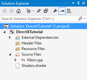
- Lesson 11: 绘制三角形
- 【DirecX 教程】Lesson 10:绘制一个三角形
- 绘制三角形
- 绘制三角形
- Direct3D 11教程2:绘制一个三角形
- 绘制彩色三角形
- 使用directx绘制三角形
- 使用CSS绘制三角形
- 纯css绘制三角形
- 2_DirectX_绘制三角形
- UIBezierPath绘制三角形
- CSS 三角形绘制方法
- DirectX9 示例:绘制三角形
- GLSurfaceView 绘制三角形
- css绘制三角形方法
- OpenGL2-绘制三角形
- CSS绘制三角形
- CSS绘制三角形
- python之re模块
- Hibernate 的七种映射关系
- 删除链表中间节点
- 键盘录入两个文件路径,将其中一个文件夹中的所有的文件复制到另一个文件中
- JAVASE第2天笔记
- Lesson 11: 绘制三角形
- 简单小程序敲着练手额~
- JAVASE第3天笔记
- JAVASE第4天笔记
- JAVASE第5天笔记
- 动态规划总结
- JAVASE第6天笔记
- install salt & initial configuration(centos7)
- Vollery网络框架的源码分析