PCIe设备漫游记----BIOS篇
来源:互联网 发布:java编程工具 知乎 编辑:程序博客网 时间:2024/05/21 12:50
转自:http://blog.csdn.net/saloon_yuan/article/details/7519852
初步了解完PCI总线标准之后,我们接下来正式开始PCIe设备的漫游之旅。从我们按下PC的电源按钮开始,BIOS就接管系统控制权开始工作,它会先进行一些内存和设备的初始化工作(当然,也包括我们的PCI设备),由于商业上的原因,Phoenix等厂商的BIOS代码需要授权协议,在此,我们以另外一个款开源BIOS(openbios)为例,来剖析BIOS中,我们的PCIe设备是如何被找到以及初始化的。

PCI设备的扫描是基于深度优先搜索算法(DFS:Depth First Search),也就是说,下级分支最多的PCI桥将最先完成其子设备的扫描。下面我们以图片来具体说明,BIOS是如何一步步完成PCI 设备扫描的。
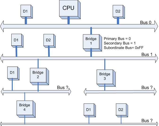
第一步:
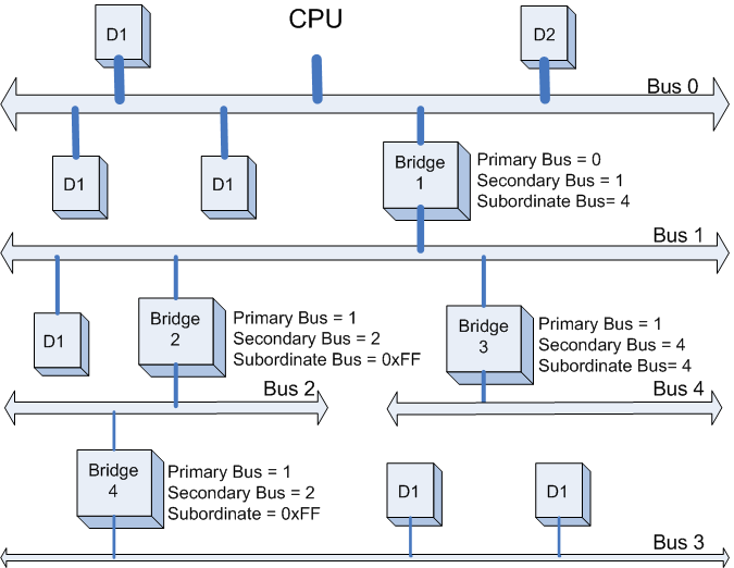
PCI Host 主桥扫描Bus 0上的设备(在一个处理器系统中,一般将与HOST主桥直接相连的PCI总线被命名为PCI Bus 0),系统首先会忽略Bus 0上的D1,D2等不会挂接PCI桥的设备,主桥发现Bridge 1后,将Bridge1 下面的PCI Bus定为 Bus 1,系统将初始化Bridge 1的配置空间,并将该桥的Primary Bus Number 和 Secondary Bus Number寄存器分别设置成0和1,以表明Bridge1 的上游总线是0,下游总线是1,由于还无法确定Bridge1下挂载设备的具体情况,系统先暂时将Subordinate Bus Number设为0xFF。如下图所示:
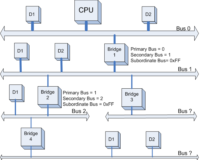
第二步:
系统开始扫描Bus 1,将会发现Bridge 2。系统将Bridge 2下面的PCI Bus定为Bus 2,并将该桥的Primary Bus Number 和 Secondary Bus Number寄存器分别设置成1和2,和上一步一样暂时把Bridge 2 的Subordinate Bus Number设为0xFF。如下图所示:
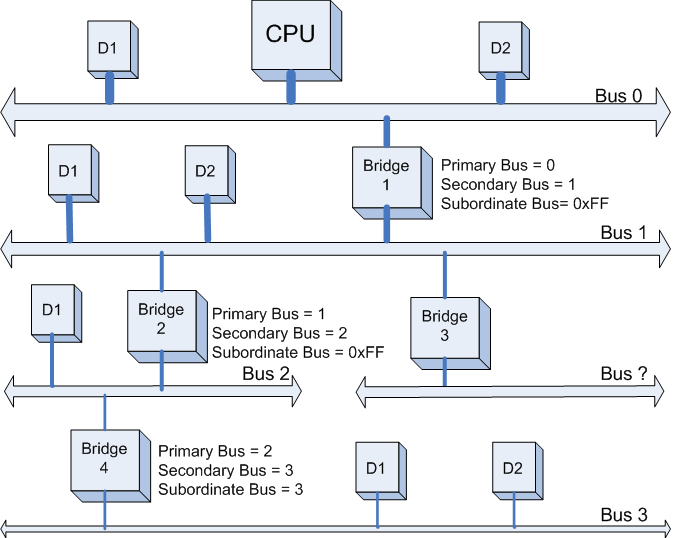
第三步:
系统继续扫描Bus 2,将会发现Bridge 4。系统将Bridge 4下面的PCI Bus定为Bus 3,并将该桥的Primary Bus Number 和 Secondary Bus Number寄存器分别设置成2和3,此后
系统继续扫描后发现Bus 3 下面已经没有任何Bridge了,意味着该PCI总线下已经没有任何挂载下游总线了,因此Bridge 4的Subordinate Bus Number的值已经可以确定为3了。
如下图所示:
第四步:
完成Bus 3的扫描后,系统返回到Bus 2继续扫描,发现Bus 2下面已经没有其他Bridge了。此时Bridge 2的Subordinate Bus Number的值也已经可以确定为3了。如下图所示:

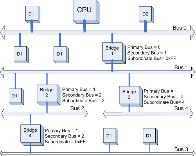
第五步:
完成Bus 2的扫描后,系统返回到Bus1继续扫描,会发现Bridge 3,系统将Bridge 3下面的PCI Bus定为Bus 4。并将Bridge 4的Primary Bus Number 和 Secondary Bus Number寄存器分别设置成1和4,此后系统继续扫描后发现Bus 4 下面已经没有任何Bridge了,意味着该PCI总线下已经没有挂载任何下游总线了,因此Bridge 3 的Subordinate Bus Number的值已经可以确定为4了。如下图所示:
第六步:
完成Bus 4的扫描后,系统返回到Bus 1继续扫描, 发现Bus 1下面已经没有其他Bridge了。此时Bridge 1的Subordinate Bus Number的值已经可以确定为4,系统返回Bus 0继续扫描(Bus 0下如果有其他它Bridge,将重复上述的步骤进行扫描)。至此,本例中的整个PCI的设备扫描已经完成了。最终的设备和总线的扫描结果如下图所示。
了解了上面PCI设备扫描的大概流程,我们接下来看看Bios代码中具体是如何实现这些扫描的。
一般来说,我们可以通过两个寄存器来访问PCI的配置空间(寄存器CONFIG_ADDRESS与CONFIG_DATA),在x86体系下,这两个寄存器分别对应0xCF8和0xCFC端口,对配置空间的访问都是通过对这两个寄存器的读写来实现先。CONFIG_ADDRESS寄存器的具体位组成如下图所示:
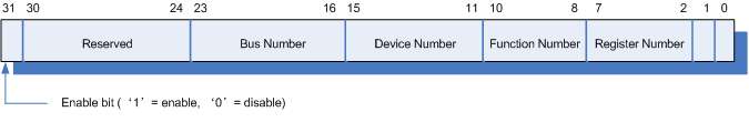
Bus Number : 总线号(8 bit),范围0--255。
Device Number: 设备号(5 bit),范围0--31。
Function Number: 功能号(3 bit),范围0--7。
Register Number: 寄存器号(6 bit),范围0--63 (配置空间一共256个字节,分割成64个4字节的寄存器,从0--63编号)。
因此,BIOS中PCI配置空间的读写可以封装成下面的函数:
static inline uint32_t pci_config_read32(pci_addr dev, uint8_t reg){ outl(dev | reg, 0xcf8); return inl(0xcfc | reg);}static inline void pci_config_write32(pci_addr dev, uint8_t reg, uint32_t val){ outl(dev | reg, 0xcf8); outl(val, 0xcfc);}总体来说。该BIOS扫描过程中调用如下几个主要的函数:
ob_pci_init ----> ob_scan_pci_bus ----> pci_find_device ----> ob_pci_configure
下面我们来具体看看代码,首先BIOS执行ob_pci_init(void)函数
int ob_pci_init(void){ int bus; unsigned long mem_base, io_base;char *path;#ifdef CONFIG_DEBUG_PCIprintk("Initializing PCI devices...\n");#endif/* brute force bus scan *//* Find all PCI bridges */ //获取系统指定的memeory与I/O空间的范围,分配给PCIe设备。mem_base = arch->mem_base; /* I/O ports under 0x400 are used by devices mapped at fixed location. */ io_base = arch->io_base + 0x400;path = strdup(""); /*遍历256条总线*/ for (bus = 0; bus<0x100; bus++) {ob_scan_pci_bus(bus, &mem_base, &io_base, &path);}free(path);return 0;}总线扫描具体实现:
static void ob_scan_pci_bus(int bus, unsigned long *mem_base, unsigned long *io_base, char **path){int devnum, fn, is_multi, vid, did;unsigned int htype;pci_addr addr;pci_config_t config; const pci_dev_t *pci_dev;uint32_t ccode;uint8_t class, subclass, iface, rev;activate_device("/");for (devnum = 0; devnum < 32; devnum++) {is_multi = 0;for (fn = 0; fn==0 || (is_multi && fn<8); fn++) {#ifdef CONFIG_XBOXif (pci_xbox_blacklisted (bus, devnum, fn))continue;#endifaddr = PCI_ADDR(bus, devnum, fn); /*获取设备配置空间地址*/vid = pci_config_read16(addr, PCI_VENDOR_ID); /*获取Vendor ID*/did = pci_config_read16(addr, PCI_DEVICE_ID); /*获取Device ID*/if (vid==0xffff || vid==0)continue;ccode = pci_config_read16(addr, PCI_CLASS_DEVICE);class = ccode >> 8;subclass = ccode;iface = pci_config_read8(addr, PCI_CLASS_PROG);rev = pci_config_read8(addr, PCI_REVISION_ID);pci_dev = pci_find_device(class, subclass, iface,/*具体设备查找以及初始化*/ vid, did);#ifdef CONFIG_DEBUG_PCIprintk("%x:%x.%x - %x:%x - ", bus, devnum, fn,vid, did);#endifhtype = pci_config_read8(addr, PCI_HEADER_TYPE);if (fn == 0)is_multi = htype & 0x80;if (pci_dev == NULL || pci_dev->name == NULL) snprintf(config.path, sizeof(config.path), "%s/pci%x,%x", *path, vid, did);else snprintf(config.path, sizeof(config.path), "%s/%s", *path, pci_dev->name);#ifdef CONFIG_DEBUG_PCIprintk("%s - ", config.path);#endifconfig.dev = addr & 0x00FFFFFF;REGISTER_NAMED_NODE(ob_pci_node, config.path);activate_device(config.path); ob_pci_configure(addr, &config, mem_base, io_base); /*配置设备的配置空间*/ob_pci_add_properties(addr, pci_dev, &config); if (class == PCI_BASE_CLASS_BRIDGE && (subclass == PCI_SUBCLASS_BRIDGE_HOST || subclass == PCI_SUBCLASS_BRIDGE_PCI)) {/* host or bridge */free(*path);*path = strdup(config.path);}}}device_end();}具体某条总线上的设备扫描由以下函数实现:<pre name="code" class="cpp">const pci_dev_t *pci_find_device (uint8_t class, uint8_t subclass, uint8_t iface, uint16_t vendor, uint16_t product){ int (*config_cb)(const pci_config_t *config); const pci_class_t *pclass; const pci_subclass_t *psubclass; const pci_iface_t *piface; const pci_dev_t *dev; const void *private; pci_dev_t *new; const char *name, *type; name = "unknown"; type = "unknown"; config_cb = NULL; private = NULL; if (class == 0x00 && subclass == 0x01) { /* Special hack for old style VGA devices */ class = 0x03; subclass = 0x00; } else if (class == 0xFF) { /* Special case for misc devices */ dev = misc_pci; goto find_device; } if (class > (sizeof(pci_classes) / sizeof(pci_class_t))) { name = "invalid PCI device"; type = "invalid"; goto bad_device; } pclass = &pci_classes[class]; name = pclass->name; type = pclass->type; for (psubclass = pclass->subc; ; psubclass++) { if (psubclass->subclass == 0xFF) goto bad_device; if (psubclass->subclass == subclass) { if (psubclass->name != NULL) name = psubclass->name; if (psubclass->type != NULL) type = psubclass->type; if (psubclass->config_cb != NULL) { config_cb = psubclass->config_cb; } if (psubclass->private != NULL) private = psubclass->private; if (psubclass->iface != NULL) break; dev = psubclass->devices; goto find_device; } } for (piface = psubclass->iface; ; piface++) { if (piface->iface == 0xFF) { dev = psubclass->devices; break; } if (piface->iface == iface) { if (piface->name != NULL) name = piface->name; if (piface->type != NULL) type = piface->type; if (piface->config_cb != NULL) { config_cb = piface->config_cb; } if (piface->private != NULL) private = piface->private; dev = piface->devices; break; } }find_device: if (dev == NULL)goto bad_device; for (;; dev++) { if (dev->vendor == 0xFFFF && dev->product == 0xFFFF) { goto bad_device; } if (dev->vendor == vendor && dev->product == product) { if (dev->name != NULL) name = dev->name; if (dev->type != NULL) type = dev->type; if (dev->config_cb != NULL) { config_cb = dev->config_cb; } if (dev->private != NULL) private = dev->private; new = malloc(sizeof(pci_dev_t)); if (new == NULL) return NULL; new->vendor = vendor; new->product = product; new->type = type; new->name = name; new->model = dev->model; new->compat = dev->compat; new->acells = dev->acells; new->scells = dev->scells; new->icells = dev->icells; new->config_cb = config_cb; new->private = private; return new; } }bad_device: printk("Cannot manage '%s' PCI device type '%s':\n %x %x (%x %x %x)\n", name, type, vendor, product, class, subclass, iface); return NULL;}配置具体设备的配置空间static void ob_pci_configure(pci_addr addr, pci_config_t *config, unsigned long *mem_base, unsigned long *io_base){uint32_t smask, omask, amask, size, reloc, min_align; unsigned long base;pci_addr config_addr;int reg;uint8_t irq_pin, irq_line; /*配置中断引脚与中断编号*/irq_pin = pci_config_read8(addr, PCI_INTERRUPT_PIN);if (irq_pin) {config->irq_pin = irq_pin;irq_pin = (((config->dev >> 11) & 0x1F) + irq_pin - 1) & 3;irq_line = arch->irqs[irq_pin];pci_config_write8(addr, PCI_INTERRUPT_LINE, irq_line);config->irq_line = irq_line;} elseconfig->irq_line = -1; /*配置memory空间和I/O空间*/omask = 0x00000000;for (reg = 0; reg < 7; reg++) {config->assigned[reg] = 0x00000000;config->sizes[reg] = 0x00000000;if ((omask & 0x0000000f) == 0x4) {/* 64 bits memory mapping */continue;}if (reg == 6)config_addr = PCI_ROM_ADDRESS;elseconfig_addr = PCI_BASE_ADDR_0 + reg * 4;config->regions[reg] = pci_config_read32(addr, config_addr);/* get region size */pci_config_write32(addr, config_addr, 0xffffffff);smask = pci_config_read32(addr, config_addr);if (smask == 0x00000000 || smask == 0xffffffff)continue;if (smask & 0x00000001 && reg != 6) {/* I/O space */base = *io_base;min_align = 1 << 7;amask = 0x00000001;pci_config_write16(addr, PCI_COMMAND, pci_config_read16(addr, PCI_COMMAND) | PCI_COMMAND_IO);} else {/* Memory Space */base = *mem_base;min_align = 1 << 16;amask = 0x0000000F;if (reg == 6) {smask |= 1; /* ROM */}pci_config_write16(addr, PCI_COMMAND, pci_config_read16(addr, PCI_COMMAND) | PCI_COMMAND_MEMORY);}omask = smask & amask;smask &= ~amask;size = (~smask) + 1;config->sizes[reg] = size;reloc = base;if (size < min_align)size = min_align;reloc = (reloc + size -1) & ~(size - 1);if (*io_base == base) {*io_base = reloc + size;reloc -= arch->io_base;} else {*mem_base = reloc + size;}pci_config_write32(addr, config_addr, reloc | omask);config->assigned[reg] = reloc | omask;}}通过以上这些步骤,Bios就完成了所有PCI设备的扫描,并且为每个设备分配好了系统资源。<br></pre><pre></pre> - PCIe设备漫游记----BIOS篇
- PCIe设备漫游记----BIOS篇
- PCIe设备漫游记----BIOS篇
- PCIe设备漫游记----BIOS篇
- PCIe设备漫游记----驱动加载篇
- PCIe设备漫游记----寄存器读写篇
- PCIe设备漫游记----驱动加载篇
- PCIe设备漫游记----设备打开/关闭篇
- PCIe SSD 性能调优--PCIe,BIOS配置篇
- PCIe设备,功能,总线
- PCIe设备发现过程
- 大话PCIe:设备枚举
- Q35+uefi or bios+legacy // PCI | PCIE
- PCIe设备的配置空间
- PCIE 设备扫描的过程
- PCIE 设备扫描的过程
- pcie设备枚举(转载)
- pcie对设备的枚举
- Android系列之ActionBar
- pdf中如何编辑添加附件
- 基于zookeeper的hadoop HA实现
- Android App耗电量统计
- windows上安装tensorflow
- PCIe设备漫游记----BIOS篇
- 算法3:动态规划(二)——背包问题
- css垂直居中
- 操作系统内存管理
- 高精度加法
- 基于直方图均衡化的激光水下图像处理
- leetcode -- Binary search (5)
- Node.js+express的接口适配get和post并输出json
- js 实现循环里延迟加载或者延迟方法