Motor Drive Forum Top FAQs Part 1: How to read a motor driver datasheet
来源:互联网 发布:java 运行时代理 编辑:程序博客网 时间:2024/06/07 07:51
https://e2e.ti.com/blogs_/b/motordrivecontrol/archive/2015/05/12/-motor-drive-forum-top-faqs-part-1_3a00_-how-to-read-a-motor-driver-datasheet
Many of the questions on the forums are resolvable by taking a look at the device datasheet. “Read the manual” goes by many names in different industries, but it’s all the same idea. Although it sounds simple, knowing how to navigate the datasheet allows you to quickly find the information you require. So let’s review some of the more important sections in a TI motor driver datasheet.
Front page
The front page of the datasheet gives you a big-picture idea of what the device does and whether or not it is applicable to your system. It includes the device name, a description, features, a simple diagram and several other key items:
- Features: highlights of the device’s capabilities. This section often contains information about operating ranges, device integration, protection features and a variety of other items (Figure 1).
- Applications: this is a list of common applications for which the device was designed. It is not a comprehensive list.
- Description: a detailed summary of the device and its capabilities.
- Device information: information about the various packages the device is available in (Figure 2).
- Diagrams: these often show a simplified block diagram of the device or highlight one of its key features (Figure 3).
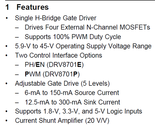
Figure 1: A typical features section
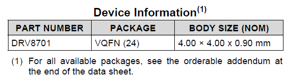
Figure 2: Device information
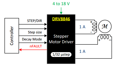
Figure 3: Block diagrams
Recommended operating conditions
The recommended operating conditions (Figure 4) are the key limits within which the device can function. Important items to take note of in a motor driver datasheet include the following:
- Power-supply voltage range.
- Low-dropout regulator (LDO) external load current.
- Output current capability.
- Maximum input frequency.
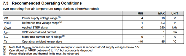
Figure 4: Recommended operating conditions
Electrical characteristics
The electrical characteristics are presented as a table of the device parameters and specifications. This includes information about regulator output voltages, logic voltage levels, timing specifications, current capability, RDS(on) and protection features.
Two important specifications are the metal-oxide semiconductor field-effect transistor (MOSFET) RDS(on) and protection-circuit parameters. The RDS(on) is the main limiting factor in a motor driver’s current capability. As current increases through the MOSFET, so will the heat generated (P = I2R). There are generally parameters for several different conditions (Figure 5).
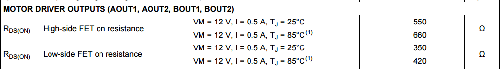
Figure 5: Motor driver outputs
The protection circuits section describes the various levels and timings of the integrated protection schemes (Figure 6). System designers often confuse the protection circuits with a device issue. These values can help debug which system issue is causing the motor driver to take a protective action.
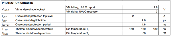
Figure 6: Protection circuits
Functional block diagram
The functional block diagram is a visual representation of the integrated circuit (Figure 7). It provides a general understanding about the internal workings of the motor driver. You can refer to the block diagram to determine how the power-supply tree is configured, how outputs should be connected, and how the logic input/outputs are set up.
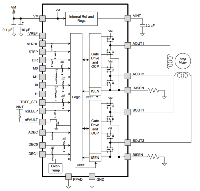 Figure 7: Functional block diagram
Layout example
Poor layout and board design is one of the top issues on the TI E2E forums. Layout issues often stem from improper placement of bypass capacitors and poor grounding schemes. The datasheet provides an entire section dedicated to layout tips/guidelines and even provides an example layout to follow (Figure 8). Ensuring proper layout of the motor driver will ensure that it performs to its specifications.
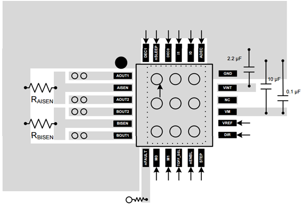
Figure 8: Layout example
Packaging information
Packaging information is often buried near the end of the datasheet, but it is just as important. This section describes the physical dimensions and properties of the device package (Figures 9 and 10). It also provides a recommended land pattern to follow for the printed circuit board (PCB) design. Using this information will help ensure that the device is properly affixed to the PCB when it’s time to assemble the board.
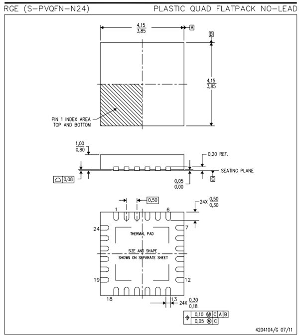
Figure 9: Physical dimensions and properties of the device package
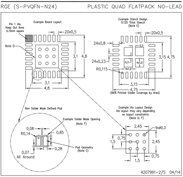
Figure 10: Physical dimensions and properties of the device package
Just remember, even in this day and age, it still helps to take a glance at the datasheet. If you have any questions, feel free to post in the comments section below.
- Motor Drive Forum Top FAQs Part 1: How to read a motor driver datasheet
- Motor Drive forum Top FAQs Part 2: How to estimate motor regeneration and VM pumping
- How to Read a Datasheet
- motor
- motor joint
- UAV Motor
- Arduino: L293D for a DC motor
- 如何阅读英文数据手册(How to read a datasheet)
- How to drive a female teacher crazy
- How to Read a Book (1)
- How to READ a technical article 1
- shaded-pole-motor
- beep 和 motor
- ORIENTAL MOTOR 2GK10X
- Vibrator motor驱动
- VCM,PIEZO motor 概念
- motor的使用
- dsPIC33F电机控制Motor
- java自学笔记11:java必须要了解的常用类
- 正则表达式学习
- 基于Python3.6和Opencv3的活动轮廓模型--CV和RSF
- python数据结构之图深度优先和广度优先
- 《UML用户指南》笔记
- Motor Drive Forum Top FAQs Part 1: How to read a motor driver datasheet
- java 网络编程的网络模型7层介绍:
- 2017总结,
- iptables规则备份和恢复、firewall的9个zone、关于zone的操作和关于service的操作
- centos7下安装nginx
- Android NDK实现增量更新
- Flask框架知识系列之三
- 将数据快速读入R—readr和readxl包
- Java设计模式-工厂方法模式