serial setting
来源:互联网 发布:js fetch post 编辑:程序博客网 时间:2024/06/06 01:13
Serial port


In computing, aserial port is a serial communication physical interface through which information transfers in or out onebit at a time (in contrast to aparallel port).[1] Throughout most of the history of personal computers, data was transferred through serial ports connected the computer to devices such asterminals and various peripherals.
While such interfaces as Ethernet, FireWire, and USB all send data as a serial stream, the term "serial port" usually identifies hardware more or less compliant to theRS-232 standard, intended to interface with amodem or with a similar communication device.
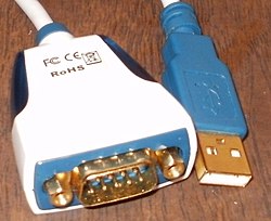
Modern computers without serial ports may require serial-to-USB converters to allow compatibility with RS 232 serial devices. Serial ports are still used in applications such as industrial automation systems, scientific instruments,shop till systems and some industrial and consumer products.Server computers may use a serial port as a control console for diagnostics. Network equipment (such as routers and switches) often use serial console for configuration. Serial ports are still used in these areas as they are simple, cheap and their console functions are highly standardized and widespread. A serial port requires very little supporting software from the host system.
Contents
[hide]- 1Hardware
- 1.1DTE and DCE
- 1.2Connectors
- 1.3Pinouts
- 1.4Hardware abstraction
- 2Common applications for serial ports
- 3Settings
- 3.1Speed
- 3.2Data bits
- 3.3Parity
- 3.4Stop bits
- 3.5Conventional notation
- 3.6Flow control
- 4"Virtual" serial ports
- 5See also
- 6References
- 7External links
[edit]Hardware

Some computers, such as the IBM PC, used an integrated circuit called a UART, that converted characters to (and from) asynchronous serial form, and automatically looked after the timing and framing of data. Very low-cost systems, such as some earlyhome computers, would instead use theCPU to send the data through an output pin, using the bit-banging technique. Before large-scale integration (LSI) UART integrated circuits were common, a minicomputer or microcomputer would have a serial port made of multiple small-scale integrated circuits to implement shift registers, logic gates, counters, and all the other logic for a serial port.
Early home computers often had proprietary serial ports with pinouts and voltage levels incompatible with RS-232. Inter-operation with RS-232 devices may be impossible as the serial port cannot withstand the voltage levels produced and may have other differences that "lock in" the user to products of a particular manufacturer.
Low-cost processors now allow higher-speed, but more complex, serial communication standards such asUSB and FireWire to replace RS-232. These make it possible to connect devices that would not have operated feasibly over slower serial connections, such as mass storage, sound, and video devices.
Many personal computer motherboards still have at least one serial port, even if accessible only through apin header. Small-form-factor systems and laptops may omit RS-232 connector ports to conserve space, but the electronics are still there. RS-232 has been standard for so long that the circuits needed to control a serial port became very cheap and often exist on a single chip, sometimes also with circuitry for a parallel port.
[edit]DTE and DCE
The individual signals on a serial port are unidirectional and when connecting two devices the outputs of one device must be connected to the inputs of the other. Devices are divided into two categories "data terminal equipment" (DTE) and "data circuit-terminating equipment" (DCE). A line that is an output on a DTE device is an input on a DCE device and vice-versa so a DCE device can be connected to a DTE device with a straight wired cable. Conventionally, computers and terminals are DTE while modems and perhipherals are DCE.
If it is necessary to connect two DTE devices (or two DCE devices but that is more unusual) a special cable known as anull-modem cable must be used.
[edit]Connectors
While the RS-232 standard originally specified a 25-pin D-type connector, many designers of personal computers chose to implement only a subset of the full standard: they traded off compatibility with the standard against the use of less costly and more compact connectors (in particular the DE-9 version used by the original IBM PC-AT). The desire to supply serial interface cards with two ports required that IBM reduce the size of the connector to fit onto a single card back panel. A DE-9 connector also fits onto a card with a second DB-25 connector that was similarly changed from the original Centronics-style connector. Starting around the time of the introduction of the IBM PC-AT, serial ports were commonly built with a 9-pin connector to save cost and space. However, presence of a 9-pin D-subminiature connector is not sufficient to indicate the connection is in fact a serial port, since this connector was also used for video, joysticks, and other purposes.
Some miniaturized electronics, particularly graphing calculators and hand-held amateur and two-way radio equipment, have serial ports using a phone connector, usually the smaller 2.5 or 3.5 mm connectors and use the most basic 3-wire interface.
Many models of Macintosh favored the related RS-422 standard, mostly using German Mini-DIN connectors, except in the earliest models. The Macintosh included a standard set of two ports for connection to a printer and a modem, but somePowerBook laptops had only one combined port to save space.
The standard specifies 20 different signal connections. Since most devices use only a few signals, smaller connectors can often be used. For example, the 9 pinDE-9 connector was used by most IBM-compatible PCs since the IBM PC AT, and has been standardized as TIA-574. More recently,modular connectors have been used. Most common are8P8C connectors. StandardEIA/TIA 561 specifies a pin assignment, but the "Yost Serial Device Wiring Standard"[2] invented by Dave Yost (and popularized by the Unix System Administration Handbook) is common on Unix computers and newer devices from Cisco Systems. Many devices don't use either of these standards. 10P10C connectors can be found on some devices as well. Digital Equipment Corporation defined their own DECconnect connection system which was based on the Modified Modular Jack (MMJ) connector. This is a 6 pin modular jack where the key is offset from the center position. As with the Yost standard, DECconnect uses a symmetrical pin layout which enables the direct connection between two DTEs. Another common connector is the DH10 header connector common on motherboards and add-in cards which is usually converted via a cable to the more standard 9 pinDE-9 connector (and frequently mounted on a free slot plate or other part of the housing).
[edit]Pinouts
The following table lists commonly used RS-232 signals and pin assignments.[3]
(TIA-574)
The signals are named from the standpoint of the DTE, for example, an IBM-PC compatible serial port.The ground signal is a common return for the other connections; it appears on two pins in the Yost standard but is the same signal. The DB-25 connector includes a second "protective ground" on pin 1. Connecting this to pin 7 (signal reference ground) is a common practice but not essential.
Note that EIA/TIA 561 combines DSR and RI,[7][8] and the Yost standard combines DSR and DCD.
[edit]Hardware abstraction
Operating systems usually use a symbolic name to refer to the serial ports of a computer.
Unix-like operating systems usually label the serial port devices/dev/tty* (TTY is a common trademark-free abbreviation for teletype) where* represents a string identifying the terminal device; the syntax of that string depends on the operating system and the device. OnLinux, 8250/16550 UART hardware serial ports are named/dev/ttyS*, USB adapters appear as /dev/ttyUSB* and various types of virtual serial ports do not necessarily have names starting withtty.
The Microsoft MS-DOS andWindows environments refer to serial ports as COM ports: COM1, COM2,..etc.
[edit]Common applications for serial ports
The RS-232 standard is used by many specialized and custom-built devices. This list includes some of the more common devices that are connected to the serial port on a PC. Some of these such as modems and serial mice are falling into disuse while others are readily available.
Serial ports are very common on most types of microcontroller, where they can be used to communicate with a PC or other serial devices.
- Dial-up modems
- GPS receivers (typicallyNMEA 0183 at4,800 bit/s)
- Bar code scanners and otherpoint of sale devices
- LED andLCD text displays
- Satellite phones, low-speed satellite modems and other satellite based transceiver devices
- Flat-screen (LCD and Plasma) monitors to control screen functions by external computer, other AV components or remotes
- Test and measuring equipment such as digital multimeters and weighing systems
- Updating Firmware on various consumer devices.
- Some CNC controllers
- Uninterruptible power supply
- Stenography or Stenotype machines.
- Software debuggers that run on a second computer.
- Industrial field buses
- Printers
- Computer terminal,teletype
- Older digital cameras
- Networking (MacintoshAppleTalk usingRS-422 at 230.4 kbit/s)
- Serial mouse
- Older GSM mobile phones
- Some Telescopes
Since the control signals for a serial port can be easily turned on and off by a switch, some applications used the control lines of a serial port to monitor external devices, without exchanging serial data. A common commercial application of this principle was for some models of uninterruptible power supply which used the control lines to signal "loss of power", "battery low alarm" and other status information. At least someMorse code training software used a code key connected to the serial port, to simulate actual code use. The status bits of the serial port could be sampled very rapidly and at predictable times, making it possible for the software to decipher Morse code.
[edit]Settings
Many settings are required for serial connections used for asynchronous start-stop communication, to select speed, number of data bits per character, parity, and number of stop bits per character. In modern serial ports using aUART integrated circuit, all settings are usually software-controlled; hardware from the 1980s and earlier may require setting switches or jumpers on a circuit board. One of the simplifications made in such serial bus standards as Ethernet, FireWire, and USB is that many of those parameters have fixed values so that users can not and need not change the configuration; the speed is either fixed or automatically negotiated. Often if the settings are entered incorrectly the connection will not be dropped; however, any data sent will be received on the other end as nonsense.
[edit]Speed
Serial ports use two-level (binary) signaling, so the data rate in bits per second is equal to the symbol rate inbauds. A standard series of rates is based on multiples of the rates for electromechanicalteleprinters; some serial ports allow many arbitrary rates to be selected. The port speed and device speed must match. The capability to set a bit rate does not imply that a working connection will result. Not all bit rates are possible with all serial ports. Some special-purpose protocols such asMIDI for musical instrument control, use serial data rates other than the teleprinter series. Some serial port systems can automatically detect the bit rate.
The speed includes bits for framing (stop bits, parity, etc.) and so the effective data rate is lower than the bit transmission rate. For example with8-N-1 character framing only 80% of the bits are available for data (for every eight bits of data, two more framing bits are sent).
Bit rates commonly supported include 75, 110, 300, 1200, 2400, 4800, 9600, 19200, 38400, 57600 and 115200 bit/s.[9]Crystal oscillators with a frequency of 1.843200 MHz are sold specifically for this purpose. This is 16 times the fastest bit rate and the serial port circuit can easily divide this down to lower frequencies as required.
[edit]Data bits
The number of data bits in each character can be 5 (for Baudot code), 6 (rarely used), 7 (for true ASCII), 8 (for any kind of data, as this matches the size of a byte), or 9 (rarely used). 8 data bits are almost universally used in newer applications. 5 or 7 bits generally only make sense with older equipment such as teleprinters.
Most serial communications designs send the data bits within each byte LSB (Least significant bit) first. This standard is also referred to as "little endian." Also possible, but rarely used, is "big endian" or MSB (Most Significant Bit) first serial communications; this was used, for example, by theIBM 2741 printing terminal. (SeeBit numbering for more about bit ordering.) The order of bits is not usually configurable within the serial port interface. To communicate with systems that require a different bit ordering than the local default, local software can re-order the bits within each byte just before sending and just after receiving.
[edit]Parity
Parity is a method of detecting errors in transmission. When parity is used with a serial port, an extra data bit is sent with each data character, arranged so that the number of 1 bits in each character, including the parity bit, is always odd or always even. If a byte is received with the wrong number of 1s, then it must have been corrupted. However, an even number of errors can pass the parity check.
Electromechanical teleprinters were arranged to print a special character when received data contained a parity error, to allow detection of messages damaged byline noise. A single parity bit does not allow implementation of error correction on each character, and communication protocols working over serial data links will have higher-level mechanisms to ensure data validity and request retransmission of data that has been incorrectly received.
The parity bit in each character can be set to none (N), odd (O), even (E), mark (M), or space (S). None means that no parity bit is sent at all. Mark parity means that the parity bit is always set to the mark signal condition (logical 1) and likewise space parity always sends the parity bit in the space signal condition. Aside from uncommon applications that use the 9th (parity) bit for some form of addressing or special signalling, mark or space parity is uncommon, as it adds no error detection information. Odd parity is more useful than even, since it ensures that at least one state transition occurs in each character, which makes it more reliable. The most common parity setting, however, is "none", with error detection handled by a communication protocol.
[edit]Stop bits
Stop bits sent at the end of every character allow the receiving signal hardware to detect the end of a character and to resynchronise with the character stream. Electronic devices usually use one stop bit. If slow electromechanicalteleprinters are used, one-and-one half or two stop bits are required.
[edit]Conventional notation
The D/P/S (Data/Parity/Stop) conventional notation specifies the framing of a serial connection. The most common usage on microcomputers is 8/N/1 (8N1). This specifies 8 data bits, no parity, 1 stop bit. In this notation, the parity bit is not included in the data bits. 7/E/1 (7E1) means that an even parity bit is added to the seven data bits for a total of eight bits between the start and stop bits. If a receiver of a 7/E/1 stream is expecting an 8/N/1 stream, half the possible bytes will be interpreted as having the high bit set.
[edit]Flow control
A serial port may use signals in the interface to pause and resume the transmission of data. For example, a slow printer might need tohandshake with the serial port to indicate that data should be paused while the mechanism advances a line.
Common hardware handshake signals (hardware flow control) use the RS-232 RTS/CTS or DTR/DSR signal circuits. Generally, the RTS and CTS are turned off and on from alternate ends to control data flow, for instance when a buffer is almost full. DTR and DSR are usually on all the time and, per the RS-232 standard and its successors, are used to signal from each end that the other equipment is actually present and powered-up. However, manufacturers have over the years built many devices that implemented non-standard variations on the standard, for example, printers that use DTR as flow control.
Another method of flow control (software flow control) uses special characters such asXON/XOFF to control the flow of data. The XON/XOFF characters are sent by the receiver to the sender to control when the sender will send data, that is, these characters go in the opposite direction to the data being sent. The circuit starts in the "sending allowed" state. When the receiver's buffers approach capacity, the receiver sends the XOFF character to tell the sender to stop sending data. Later, after the receiver has emptied its buffers, it sends an XON character to tell the sender to resume transmission. These are non-printing characters and are interpreted as handshake signals by printers, terminals, and computer systems.
XON/XOFF flow control is an example of in-band signaling, in which control information is sent over the same channel used for the data. If the XON and XOFF characters might appear in the data being sent, XON/XOFF handshaking presents difficulties, as receivers may interpret them as flow control. Such characters sent as part of the data stream must be encoded in an escape sequence to prevent this, and the receiving and sending software must generate and interpret these escape sequences. On the other hand, since no extra signal circuits are required, XON/XOFF flow control can be done on a 3 wire interface.
[edit]"Virtual" serial ports
A virtual serial port is an emulation of the standard serial port. This port is created by software which enable extra serial ports in an operating system without additional hardware installation (such asexpansion cards, etc.). It is possible to create a large number of virtual serial ports in a PC. The only limitation is the amount of resources, such as operating memory and computing power, needed to emulate many serial ports at the same time.
Virtual serial ports emulate all hardware serial port functionality, includingBaud rate, Data bits, Parity bits, Stop bits, etc. Additionally they allow controlling the data flow, emulating all signal lines (DTR/DSR/CTS/RTS/DCD/RI) and customizing pinout. Virtual serial ports are common withBluetooth and are the standard way of receiving data from Bluetooth-equipped GPS modules.
Virtual serial port emulation can be useful in case there is a lack of available physical serial ports or they do not meet the current requirements. For instance, virtual serial ports can share data between several applications from oneGPS device connected to a serial port. Another option is to communicate with any other serial devices via internet or LAN as if they are locally connected to computer (Serial-over-Ethernet technology). Two computers or applications can communicate through an emulated serial port link. Virtual serial port emulators are available for many operating systems including MacOS, Linux, and various mobile and desktop versions of Microsoft Windows.
[edit]See also
- Teleprinter
[edit]References
- ^Webopedia (2003-09-03). "What is serial port? - A Word Definition From the Webopedia Computer Dictionary". Webopedia.com. Retrieved 2009-08-07.
- ^Yost Serial Device Wiring Standard
- ^Joakim Ögren. "Serial (PC 9)".
- ^ a b Cyclom-Y Installation Manual, page 38, retrieved on 29 November 2008
- ^National Instruments Serial Quick Reference Guide, February 2007
- ^Installation Guide, DigiBoard PC/Xi, PC/16e, MC/Xi and COM/Xi Intelligent Asynchronous Serial Communications Board, pages 36-37, retrieved on 7 December 2008
- ^Hardware Book RS-232D
- ^RS-232D EIA/TIA-561 RJ45 Pinout
- ^"DCB Structure".MSDN. Microsoft. Retrieved 15 March 2011.
[edit]External links
- Serial Port Programming in Linux
- Keyboard·
- Image scanner·
- Microphone·
- Pointing device
- (
- Graphics tablet·
- Joystick·
- Light pen·
- Mouse·
- Pointing stick·
- Touchpad·
- Touchscreen·
- Trackball )
- Webcam
- (
- Softcam )
- Monitor·
- Printer·
- Speakers·
- Plotter
- Optical disc drive
- (
- CD-RW ·
- DVD+RW )
- Disk pack·
- Floppy disk·
- Memory card·
- USB flash drive
- Central processing unit (CPU)·
- Hard disk /Solid-state drive ·
- Motherboard·
- Network interface controller·
- Power supply·
- Random-access memory (RAM)·
- Sound card·
- Video card
- Ethernet·
- FireWire (IEEE 1394)·
- Parallel port·
- Serial port ·
- Universal Serial Bus (USB)
- Serial buses
- Out-of-band management
- Legacy hardware
- serial setting
- serial
- serial
- serial
- Setting
- setting
- setting
- Setting
- setting
- setting
- Setting
- Serial Programming/Serial Java
- about serial
- Serial Communication
- Serial Drivers
- Serial ATA
- usb serial
- Serial Port
- C#中的类与结构体的区别
- 基于单文档的VC++动态曲线绘制
- GCD的另一个用处是可以让程序在后台较长久的运行。
- 强制类型转换
- opencv中的矩阵解释,包括CvMat IplImage 、MAT 类型之间的转化
- serial setting
- Android特效 五种Toast详解
- 机器学习中的算法(1)-决策树模型组合之随机森林与GBDT
- 可输入文字查找ajax下拉框控件 ComBox
- vector和iterator
- 详解WPF中Flash的嵌入的两种方式
- apk签名后,优化。
- DevExpress技术社区正式开放!
- CIRCOS教程翻译 5.1——Drawing Basic Links