SR-1/Software Radio
来源:互联网 发布:中国电信网络套餐介绍 编辑:程序博客网 时间:2024/04/28 13:22
http://volodya-project.sourceforge.net/SR/SR-1/sr1.php
OverviewBefore implementing full blown software radio I needed to become familiar with CY7C68013 and to answer a few questions:
- How much data can it pump thorough ?
- How much data can linux USB driver handle without overburdening cpu too much ?
Also it would be a good idea to develop a few tools that would become useful later.
Hence, SR-1: a usb device that is just CY7C68013 without anything to pass data from.
Components
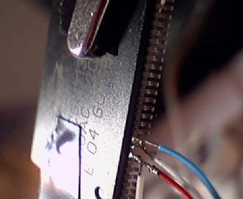
I ordered my parts from Arrow electronics website. This went ok, except that the shipping was too much. I understood why after I got three packages: a large envelope, a carton triangular box (the one to ship posters in) and a long carton box. Turns out that they shipped the parts in standard packaging, even though I ordered only few chips each. Here is a photo of the long tray CY7C68013 came in:

Not only that, but they also shipped the parts from three different locations.
Note to self: if ordering low quantity parts from Arrow Electronics again order as few different kinds as one can and get others from someplace else that ships from a single address.
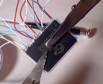
The ICs I am going to use in SR-1 are voltage regulator Linear Technology LTC1763-3.3V

and EZ-USB FX2 chip from Cypress CY7C68013

Both are surface mount components, here is a photo of them side-by-side:

Design
Ok, this should have really preceded the component part, but I thought it would be more fun to take a look at the pictures first.
Since this would be the first time I am using these ICs and there will be plenty of corners to cut later I decided to replicate most of the Cypress ATA reference design CY4611 design, but without the EEPROM and the ATA connector.
On to soldering !
The first task was to wire up the voltage regulator LTC1763 and check that it produces the correct voltage (3.3V). 
This proved easier than I thought as there was plenty of clearance between the legs of the chip. A quick test proved it functions correctly.
The hard part
Looking at the dense spacing of CY7C68013 pins prompted (yet another) trip to Radio Shack, and I purchased a "helping hands" - a kind of static holder with a magnifier glass.

The grippers turned out to be really handy, but the magnifier glass needed to be too close to work to solder comfortably. It did find its use later, though.
I decided to attach wires to each pin that I am going to use first, and then attach the wires themselves to the other parts.
The first two were easy:

The third was harder, and after trying to attach the fourth it came off:

Time to do some thinking !

After much experimentation I decided to bend every other pin up. This increased the amount of space between pins threefold. Bending is much easier with the magnifier glass.
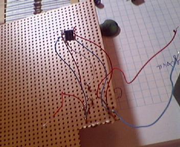
First side had the most wires. The blue ones are for ground, red ones for power and whites ones for everything else. Since both USB and I2C are serial buses there are few white wires.
Feeling somewhat exhausted I decided to continue with this project after a good nights sleep.
Fortunately attaching the rest of the wires did not prove more challenging

Assembly
Now is the time to connect everything together. This involved more soldering, during which some of the wires I so carefully attached to CY7C68013 came loose. No matter, now that I knew how to do this reattaching was trivial.

Testing
Now that SR-1 is complete it is time to plug it in.
For the first test I decided to restrict myself to USB-1.1 even though the part supports 2.0. This way I can plug it in into a USB hub which would be cheaper to replace if anything went awry. Granted, USB standard includes overcurrent and ESD protection, but some caution would not hurt. Besides, this allows me to be closer to my monitor and keyboard.
After plugging it in, Linux (2.4.16) bitterly complained about a new device that just does not want to enumerate.
After spending lots of time browsing and searching for relevant links I decided to enable debugging in USB module. Voila ! It works :))
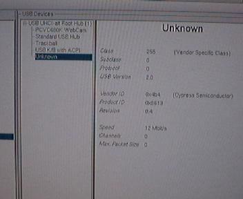
Here is a shot of dmesg output:

Apparently the debugging introduced some delays that allowed it to enumerate properly. This does not seem to be needed when connecting to USB 2.0 adaptor card so it might not be a hardware fault after all
Now that the device enumerated it was time to access its internal memory. After some quick programming I had created an fx2_programmer utility that used libusb to talk to CY7C68013.
Programming 8051
CY7C68013 contains an internal microprocessor that is opcode and register compatible with Intel 8051. Thus one can use the excellent SDCC compiler to write programs for it, instead of doing everything in machine code.
A quick update to fx2_programmer allowed me to upload Intel hex format files and test my first program that fills a predefined area with cycling integer numbers.
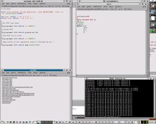
The above image is only a thumbnail, if you click on it you get the whole screenshot showing program code, compiled Intel hex format file and the dump of 8051 memory space after the program has run.
The strange xdata qualifier for the pointer p indicates that it points to the "external" memory. The reason is that 8051 is an 8 bit microprocessor and the most you can address with 8 bits is 256 bytes.. But read the manual to get the details - they are fun :)
Benchmarks
Now that everything works it is time to do some benchmarking. I connected SR-1 to ehci adaptor (no need to turn on debugging here) and wrote a small C program instructing 8051 to fire up bulk out buffers as soon as it can (ex3 in the 8051 code tarball). The best result I got was around 4 MB/sec - achieved but eliminating all 8051 code, including the NOPs recommended by the datasheet.
It turns out that changing packet size from 512 to 64 in ex3.c has little effect on the throughput. However, when I instruct fx2_programmer to read in 64 byte chunks instead of 512 the rate slows down to around 512 KB/sec.
Increasing chunk size beyound packet size yielded rediculous results - rate in excess of 50 Mb/sec for chunk size 65536.
After some digging it looks like something among usb driver and libusb screws up when user application requests to receive more than 64 byte packets, but the USB device only wants to send data in 64 byte chunks.
When I changed ex3.c to send data in 512 byte packets again things became more sensible and the rate peaked at 16 MB/sec with chunk size 2048 bytes.
The cpu utilization was quite small - less than 5%
Conclusion
The device functioned correctly. The achieved throughput rate was quite respectable and sufficient for real time data capture. The system remained almost idle during transfers.
Links and references
- Cypress Semiconductors website
- Linear Technology website
- Arrow Electronics website
- Radio Shack website
- SDCC small device C compiler website
- libusb website
- Linux USB implementation website
- fx2_programmer website
- Source code used for testing Cypress CY7C68013 chip
- The official USB website
- SR-1/Software Radio
- 我是Sr. Software Developer?
- Software Radio
- 职位分析:Sr. Embedded Software Engineer
- Software Defined Radio: The Software Communications Architecture
- Software Defined Radio for 3G
- SR
- sr
- Software Defined Radio…
- SDR (Software Defined Radio) rtl-sdr
- WinHex ver.13.9 SR-1
- WinHex.14.7.SR-1_KEYGEN-FFF
- 2008 SR
- SR锁存器
- SR-IOV
- SR-IOV
- 关于SR
- SR-IOV
- 经典限制文本字节数javaScript代码!
- C#调用存储过程
- Apple Record & Apple Company - Saybot Practice Lesson ( http://www.saybot.com/labLessonList.action )
- Linux and USB 2.0
- 图片测试
- SR-1/Software Radio
- 男人们必看六点健康建议
- Software Radio
- jdbcjdbc
- 用Visual C++开发数据库应用程序
- W32/HLLP.Philis.kl 病毒
- 日常常用的SQL语言
- I2C Drivers
- 做好个人时间管理