linux gpio模拟i2c的使用/用GPIO模拟I2C总线-2 .
来源:互联网 发布:python 打开文件夹 编辑:程序博客网 时间:2024/04/30 09:25
在drivers/i2c/busses下包含各种I2C总线驱动,如S3C2440的I2C总线驱动i2c-s3c2410.c,使用GPIO模拟I2C总线的驱动i2c-gpio.c,这里只分析i2c-gpio.c。
i2c-gpio.c它是gpio模拟I2C总线的驱动,总线也是个设备,在这里将总线当作平台设备处理,那驱动当然是平台设备驱动,看它的驱动注册和注销函数。
- 1. static int __init i2c_gpio_init(void)
- 2. {
- 3. int ret;
- 4.
- 5. ret = platform_driver_register(&i2c_gpio_driver);
- 6. if (ret)
- 7. printk(KERN_ERR "i2c-gpio: probe failed: %d\n", ret);
- 8.
- 9. return ret;
- 10. }
- 11. module_init(i2c_gpio_init);
- 12.
- 13. static void __exit i2c_gpio_exit(void)
- 14. {
- 15. platform_driver_unregister(&i2c_gpio_driver);
- 16. }
- 17. module_exit(i2c_gpio_exit);
没有什么好说的,它的初始化和注销函数就是注册和注销一个平台设备驱动,直接看它的platform_driver结构i2c_gpio_driver
- 1. static struct platform_driver i2c_gpio_driver = {
- 2. .driver = {
- 3. .name = "i2c-gpio",
- 4. .owner = THIS_MODULE,
- 5. },
- 6. .probe = i2c_gpio_probe,
- 7. .remove = __devexit_p(i2c_gpio_remove),
- 8. };
平台驱动设备放在arch/arm/mach-xxxx/board-xxx.c中
- 1. #if defined(CONFIG_I2C_GPIO) | \
- 2. defined(CONFIG_I2C_GPIO_MODULE)
- 3. static struct i2c_gpio_platform_data i2c_gpio_adapter_data = {
- 4. .sda_pin = PINID_GPMI_D05,
- 5. .scl_pin = PINID_GPMI_D04,
- 6. .udelay = 5, //100KHz
- 7. .timeout = 100,
- 8. .sda_is_open_drain = 1,
- 9. .scl_is_open_drain = 1,
- 10. };
- 11.
- 12. static struct platform_device i2c_gpio = {
- 13. .name = "i2c-gpio",
- 14. .id = 0,
- 15. .dev = {
- 16. .platform_data = &i2c_gpio_adapter_data,
- 17. .release = mxs_nop_release,
- 18. },
- 19. };
- 20. #endif
在这里struct platform_device结构中的name字段要和struct platform_driver中driver字段中name字段要相同,因为平台总线就是通过这个来判断设备和驱动是否匹配的。注意这里的id将它赋值了0,至于到底有什么用,后面再来细看。这个结构里面还包含一个最重要的数据i2c_gpio_adapter_data,它struct i2c_gpio_platform_data结构类型变量,这个结构体类型定义在include/linux/i2c-gpio.h中。
- 1. struct i2c_gpio_platform_data {
- 2. unsigned int sda_pin;
- 3. unsigned int scl_pin;
- 4. int udelay;
- 5. int timeout;
- 6. unsigned int sda_is_open_drain:1;
- 7. unsigned int scl_is_open_drain:1;
- 8. unsigned int scl_is_output_only:1;
- 9. };
这个结构体主要描述gpio模拟i2c总线,sda_pin和scl_pin表示使用哪两个IO管脚来模拟I2C总线,udelay和timeout分别为它的时钟频率和超时时间,sda_is_open_drain和scl_is_open_drain表示sda、scl这两个管脚是否是开漏(opendrain)电路,如果是设置为1,scl_is_output_only表示scl这个管脚是否只是作为输出,如果是设置为1。
回到驱动中,看其中最重要的i2c_gpio_probe。
- 1. static int __devinit i2c_gpio_probe(struct platform_device *pdev)
- 2. {
- 3. struct i2c_gpio_platform_data *pdata;
- 4. struct i2c_algo_bit_data *bit_data;
- 5. struct i2c_adapter *adap;
- 6. int ret;
- 7.
- 8. pdata = pdev->dev.platform_data;
- 9. if (!pdata)
- 10. return -ENXIO;
- 11.
- 12. ret = -ENOMEM;
- 13. adap = kzalloc(sizeof(struct i2c_adapter), GFP_KERNEL);
- 14. if (!adap)
- 15. goto err_alloc_adap;
- 16. bit_data = kzalloc(sizeof(struct i2c_algo_bit_data), GFP_KERNEL);
- 17. if (!bit_data)
- 18. goto err_alloc_bit_data;
- 19.
- 20. ret = gpio_request(pdata->sda_pin, "sda");
- 21. if (ret)
- 22. goto err_request_sda;
- 23. ret = gpio_request(pdata->scl_pin, "scl");
- 24. if (ret)
- 25. goto err_request_scl;
- 26.
- 27. if (pdata->sda_is_open_drain) {
- 28. gpio_direction_output(pdata->sda_pin, 1);
- 29. bit_data->setsda = i2c_gpio_setsda_val;
- 30. } else {
- 31. gpio_direction_input(pdata->sda_pin);
- 32. bit_data->setsda = i2c_gpio_setsda_dir;
- 33. }
- 34.
- 35. if (pdata->scl_is_open_drain || pdata->scl_is_output_only) {
- 36. gpio_direction_output(pdata->scl_pin, 1);
- 37. bit_data->setscl = i2c_gpio_setscl_val;
- 38. } else {
- 39. gpio_direction_input(pdata->scl_pin);
- 40. bit_data->setscl = i2c_gpio_setscl_dir;
- 41. }
- 42.
- 43. if (!pdata->scl_is_output_only)
- 44. bit_data->getscl = i2c_gpio_getscl;
- 45. bit_data->getsda = i2c_gpio_getsda;
- 46.
- 47. if (pdata->udelay)
- 48. bit_data->udelay = pdata->udelay;
- 49. else if (pdata->scl_is_output_only)
- 50. bit_data->udelay = 50; /* 10 kHz */
- 51. else
- 52. bit_data->udelay = 5; /* 100 kHz */
- 53.
- 54. if (pdata->timeout)
- 55. bit_data->timeout = pdata->timeout;
- 56. else
- 57. bit_data->timeout = HZ / 10; /* 100 ms */
- 58.
- 59. bit_data->data = pdata;
- 60.
- 61. adap->owner = THIS_MODULE;
- 62. snprintf(adap->name, sizeof(adap->name), "i2c-gpio%d", pdev->id);
- 63. adap->algo_data = bit_data;
- 64. adap->class = I2C_CLASS_HWMON | I2C_CLASS_SPD;
- 65. adap->dev.parent = &pdev->dev;
- 66.
- 67. /*
- 68. * If "dev->id" is negative we consider it as zero.
- 69. * The reason to do so is to avoid sysfs names that only make
- 70. * sense when there are multiple adapters.
- 71. */
- 72. adap->nr = (pdev->id != -1) ? pdev->id : 0;
- 73. ret = i2c_bit_add_numbered_bus(adap);
- 74. if (ret)
- 75. goto err_add_bus;
- 76.
- 77. platform_set_drvdata(pdev, adap);
- 78.
- 79. dev_info(&pdev->dev, "using pins %u (SDA) and %u (SCL%s)\n",
- 80. pdata->sda_pin, pdata->scl_pin,
- 81. pdata->scl_is_output_only
- 82. ? ", no clock stretching" : "");
- 83.
- 84. return 0;
- 85.
- 86. err_add_bus:
- 87. gpio_free(pdata->scl_pin);
- 88. err_request_scl:
- 89. gpio_free(pdata->sda_pin);
- 90. err_request_sda:
- 91. kfree(bit_data);
- 92. err_alloc_bit_data:
- 93. kfree(adap);
- 94. err_alloc_adap:
- 95. return ret;
- 96. }
从这句开始pdata= pdev->dev.platform_data;这不正是我们在平台设备结构中定义的数据吗。然后是使用kzalloc申请两段内存空间,一个是为结构struct i2c_adapter申请的,另一个是为结构structi2c_algo_bit_data申请的。
struct i2c_adapter结构定义在include/linux/i2c.h中
- 1. struct i2c_adapter {
- 2. struct module *owner;
- 3. unsigned int id;
- 4. unsigned int class; /* classes to allow probing for */
- 5. const struct i2c_algorithm *algo; /* the algorithm to access the bus */
- 6. void *algo_data;
- 7.
- 8. /* data fields that are valid for all devices */
- 9. u8 level; /* nesting level for lockdep */
- 10. struct mutex bus_lock;
- 11.
- 12. int timeout; /* in jiffies */
- 13. int retries;
- 14. struct device dev; /* the adapter device */
- 15.
- 16. int nr;
- 17. char name[48];
- 18. struct completion dev_released;
- 19. };
在I2C子系统中,I2C适配器使用结构struct i2c_adapter描述,代表一条实际的I2C总线。
struct i2c_algo_bit_data结构定义在include/linux/i2c-algo-bit.h中
- 1. struct i2c_algo_bit_data {
- 2. void *data; /* private data for lowlevel routines */
- 3. void (*setsda) (void *data, int state);
- 4. void (*setscl) (void *data, int state);
- 5. int (*getsda) (void *data);
- 6. int (*getscl) (void *data);
- 7.
- 8. /* local settings */
- 9. int udelay; /* half clock cycle time in us,
- 10. minimum 2 us for fast-mode I2C,
- 11. minimum 5 us for standard-mode I2C and SMBus,
- 12. maximum 50 us for SMBus */
- 13. int timeout; /* in jiffies */
- 14. };
这个结构主要用来定义对GPIO管脚的一些操作,还是回到probe中
接下来使用gpio_request去申请这个两个GPIO管脚,申请的目的是为了防止重复使用管脚。然后是根据struct i2c_gpio_platform_data结构中定义的后面三个数据对struct i2c_algo_bit_data结构中的函数指针做一些赋值操作。接下来是I2C时钟频率和超时设置,如果在struct i2c_gpio_platform_data结构中定义了值,那么就采用定义的值,否则就采用默认的值。然后是对struct i2c_adapter结构的一些赋值操作,比如指定它的父设备为这里的平台设备,前面在平台设备中定义了一个id,这里用到了,赋给了struct i2c_adapter中的nr成员,这个值表示总线号,这里的总线号和硬件无关,只是在软件上的区分。然后到了最后的主角i2c_bit_add_numbered_bus,这个函数定义在drivers/i2c/algos/i2c-algo-bit.c中
- 1. int i2c_bit_add_numbered_bus(struct i2c_adapter *adap)
- 2. {
- 3. int err;
- 4.
- 5. err = i2c_bit_prepare_bus(adap);
- 6. if (err)
- 7. return err;
- 8.
- 9. return i2c_add_numbered_adapter(adap);
- 0. }
- 1. static int i2c_bit_prepare_bus(struct i2c_adapter *adap)
- 2. {
- 3. struct i2c_algo_bit_data *bit_adap = adap->algo_data;
- 4.
- 5. if (bit_test) {
- 6. int ret = test_bus(bit_adap, adap->name);
- 7. if (ret < 0)
- 8. return -ENODEV;
- 9. }
- 10.
- 11. /* register new adapter to i2c module... */
- 12. adap->algo = &i2c_bit_algo;
- 13. adap->retries = 3;
- 14.
- 15. return 0;
- 16. }
bit_test为模块参数,这里不管它,看这样一句adap->algo= &i2c_bit_algo;
来看这个结构定义
- 1. static const struct i2c_algorithm i2c_bit_algo = {
- 2. .master_xfer = bit_xfer,
- 3. .functionality = bit_func,
- 4. };
- 1. struct i2c_algorithm {
- 2. /* If an adapter algorithm can't do I2C-level access, set master_xfer
- 3. to NULL. If an adapter algorithm can do SMBus access, set
- 4. smbus_xfer. If set to NULL, the SMBus protocol is simulated
- 5. using common I2C messages */
- 6. /* master_xfer should return the number of messages successfully
- 7. processed, or a negative value on error */
- 8. int (*master_xfer)(struct i2c_adapter *adap, struct i2c_msg *msgs,
- 9. int num);
- 10. int (*smbus_xfer) (struct i2c_adapter *adap, u16 addr,
- 11. unsigned short flags, char read_write,
- 12. u8 command, int size, union i2c_smbus_data *data);
- 13.
- 14. /* To determine what the adapter supports */
- 15. u32 (*functionality) (struct i2c_adapter *);
- 16. };
其实也没什么,就三个函数指针外加一长串注释
这个结构的master_xfer指针为主机的数据传输,具体来看bit_xfer这个函数,这个函数和I2C协议相关,I2C协议规定要先发送起始信号,才能开始进行数据的传输,最后数据传输完成后发送停止信号,看接下来代码对I2C协议要熟悉,所以这里的关键点是I2C协议。
- static int bit_xfer(struct i2c_adapter *i2c_adap,
- struct i2c_msg msgs[], int num)
- {
- struct i2c_msg *pmsg;
- struct i2c_algo_bit_data *adap = i2c_adap->algo_data;
- int i, ret;
- unsigned short nak_ok;
- bit_dbg(3, &i2c_adap->dev, "emitting start condition\n");
- /*发送起始信号*/
- i2c_start(adap);
- for (i = 0; i < num; i++) {
- pmsg = &msgs[i];
- nak_ok = pmsg->flags & I2C_M_IGNORE_NAK;
- if (!(pmsg->flags & I2C_M_NOSTART)) {
- if (i) {
- bit_dbg(3, &i2c_adap->dev, "emitting "
- "repeated start condition\n");
- i2c_repstart(adap);
- }
- ret = bit_doAddress(i2c_adap, pmsg);
- if ((ret != 0) && !nak_ok) {
- bit_dbg(1, &i2c_adap->dev, "NAK from "
- "device addr 0x%02x msg #%d\n",
- msgs[i].addr, i);
- goto bailout;
- }
- }
- if (pmsg->flags & I2C_M_RD) {
- /* read bytes into buffer*/
- ret = readbytes(i2c_adap, pmsg);
- if (ret >= 1)
- bit_dbg(2, &i2c_adap->dev, "read %d byte%s\n",
- ret, ret == 1 ? "" : "s");
- if (ret < pmsg->len) {
- if (ret >= 0)
- ret = -EREMOTEIO;
- goto bailout;
- }
- } else {
- /* write bytes from buffer */
- ret = sendbytes(i2c_adap, pmsg);
- if (ret >= 1)
- bit_dbg(2, &i2c_adap->dev, "wrote %d byte%s\n",
- ret, ret == 1 ? "" : "s");
- if (ret < pmsg->len) {
- if (ret >= 0)
- ret = -EREMOTEIO;
- goto bailout;
- }
- }
- }
- ret = i;
- bailout:
- bit_dbg(3, &i2c_adap->dev, "emitting stop condition\n");
- i2c_stop(adap);
- return ret;
- }
1.发送起始信号
i2c_start(adap);
看这个函数前,先看I2C协议怎么定义起始信号的
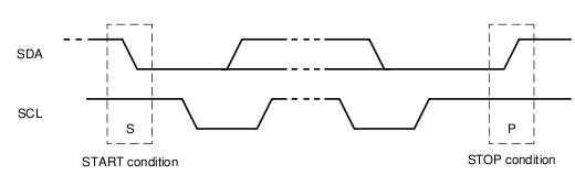
起始信号就是在SCL为高电平期间,SDA从高到低的跳变,再来看代码是怎么实现的
- 1. static void i2c_start(struct i2c_algo_bit_data *adap)
- 2. {
- 3. /* assert: scl, sda are high */
- 4. setsda(adap, 0);
- 5. udelay(adap->udelay);
- 6. scllo(adap);
- 7. }
这些setsda和setscl这些都是使用的总线的函数,在这里是使用的i2c-gpio.c中定义的函数,还记得那一系列判断赋值吗。
- #define setsda(adap, val) adap->setsda(adap->data, val)
- #define setscl(adap, val) adap->setscl(adap->data, val)
- #define getsda(adap) adap->getsda(adap->data)
- #define getscl(adap) adap->getscl(adap->data)
2.往下是个大的for循环
到了这里又不得不说这个struct i2c_msg结构,这个结构定义在include/linux/i2c.h中
- 1. struct i2c_msg {
- 2. __u16 addr; /* slave address */
- 3. __u16 flags;
- 4. #define I2C_M_TEN 0x0010 /* this is a ten bit chip address */
- 5. #define I2C_M_RD 0x0001 /* read data, from slave to master */
- 6. #define I2C_M_NOSTART 0x4000 /* if I2C_FUNC_PROTOCOL_MANGLING */
- 7. #define I2C_M_REV_DIR_ADDR 0x2000 /* if I2C_FUNC_PROTOCOL_MANGLING */
- 8. #define I2C_M_IGNORE_NAK 0x1000 /* if I2C_FUNC_PROTOCOL_MANGLING */
- 9. #define I2C_M_NO_RD_ACK 0x0800 /* if I2C_FUNC_PROTOCOL_MANGLING */
- 10. #define I2C_M_RECV_LEN 0x0400 /* length will be first received byte */
- 11. __u16 len; /* msg length */
- 12. __u8 *buf; /* pointer to msg data */
- 13. };
- linux gpio模拟i2c的使用/用GPIO模拟I2C总线-2
- linux gpio模拟i2c的使用/用GPIO模拟I2C总线-2 .
- linux gpio模拟i2c的使用/用GPIO模拟I2C总线-1
- linux gpio模拟i2c的使用/用GPIO模拟I2C总线-3
- linux gpio模拟i2c的使用/用GPIO模拟I2C总线-1
- linux gpio模拟i2c的使用/用GPIO模拟I2C总线-1 .
- linux gpio模拟i2c的使用/用GPIO模拟I2C总线-3
- linux gpio模拟i2c的使用
- linux gpio模拟i2c的使用
- linux gpio模拟i2c的使用
- linux gpio模拟i2c
- linux gpio模拟i2c
- Linux GPIO 模拟I2C
- 使用GPIO模拟I2C总线进行通信
- 使用GPIO模拟I2C总线进行通信
- 使用GPIO模拟I2C总线进行通信
- 使用GPIO模拟I2C总线进行通信
- 使用GPIO模拟I2C总线进行通信
- Java实现 输出 任意两个数之间的斐波那契序列
- 菜鸟的安卓实习之路----解析网络XML文件
- 使用vs为按钮添加后台点击事件
- 如何确定抽样统计的最小样本量(附:随机抽样统计的抽样误差Excel计算表格)
- Java设计模式透析之 —— 单例(Singleton)
- linux gpio模拟i2c的使用/用GPIO模拟I2C总线-2 .
- android中跨进程通讯的4种方式
- 项目管理精萃
- 实现按二次返回键退出程序
- hdu4540(威威猫系列故事——打地鼠)-线性dp
- java客户端调用webservice
- POJ 动态规划题目
- 移动互联网应用的发展趋势
- 目标跟踪的点跟踪技术(1)