Device Tree Customization (转)
来源:互联网 发布:teambition 类似软件 编辑:程序博客网 时间:2024/05/17 02:00
Introduction
A Device Tree is a data structure describing a system's hardware. Some hardware is "discoverable" by design (e.g. PCI buses or USB buses) while some is not (notably memory mapped peripherals). In the latter case, an operating system executable (the OS kernel) is often hard-coded for one device type. To make an operating system portable across different devices, a description of the layout of each supported hardware configuration is required to ensure the correct drivers and configuration are used. The ARM world is very heterogeneous, each SoC vendor and each board vendor wire their hardware a bit differently. In some other architectures (e.g. x86), there is a standard interface between the board firmware (BIOS) and the operating system to communicate the hardware layout - for instance, ACPI on x86. To overcome this lack of hardware description, the ARM Linux Kernel uses device trees as the preferred format of hardware description beginning around kernel version ~3.2. Prior to this change, all details of how the hardware was wired was part of the platform/machine layer and hard-coded in C structs. This became complicated as more and more ARM SoC vendors and boards appeared. More in depth information is available in thepresentation of Thomas Petazzoni about device trees.
The device-tree is not only a data structure which describe the SoC's internal memory mapped peripherals, it also allows to describe the whole board. Toradex therefore creates device trees for each module as well as each carrier board (given that the modules Linux BSP supports device tree, see table below). However, especially if a custom carrier board is built, it is likely that you as a customer need to modify the device tree too. This article provides information how to do that.
Some of our Linux BSPs make use of device tree enabled Linux kernels. The device trees are part of the Linux kernel source code and located in thearch/arm/boot/dts/ folder. For instructions of how to obtain the Linux source code for each module, refer to the articleBuild U-Boot and Linux Kernel from Source Code.
(additional/intermediate device trees may also be included, see the module specific descriptions below)
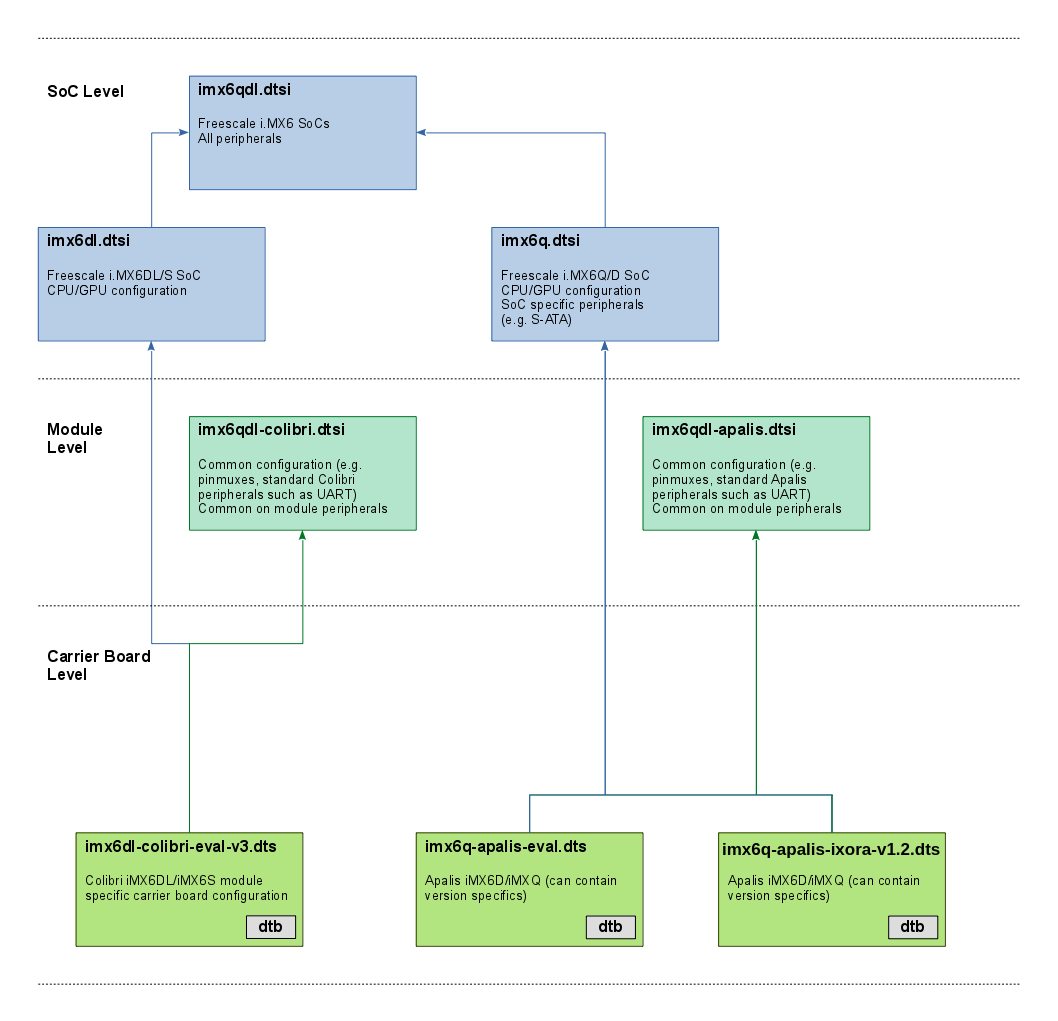
Typically, a device tree is defined at multiple levels and composed of multiple device tree files. Device tree files (dts and dtsi) may include other device tree files known as includable device tree files (dtsi). In this manner, a board level device tree file (dts) generally includes a SoC level device tree file (dtsi). To support the modular approach of Toradex products, our device tree files usually have three levels of inclusion: carrier board, module and SoC level. This is also reflected in the device tree file names, which are composed by the three levels: ${soc}-${module}-${board}.dtb
We provide a carrier board level device tree file (ie. eval-v3) that is compatible with our evaluation carrier boards. Due to the standardized hardware interfaces of the Colibri and Apalis modules, this device tree file often also works for other carrier boards (e.g. our evaluation board device trees do work on the smaller carrier boards like Iris or Ixora). However, a custom device tree may still be required for a custom carrier board to allow enabling non (Colibri/Apalis) standard devices such as secondary Ethernet or disabling unused devices (preventing unnecessary drivers from loading and reducing boot time).
Compile
The Linux kernel needs device tree binaries (*.dtb) to boot. These binaries are generated by the device tree compiler from the device tree source files. The compiler is part of the Linux sources and is automatically built if needed.The kernel build system provides the dtbs target which compiles all device trees which are compatible to the current kernel configuration.ARCH and CROSS_COMPILE must be set and the kernel must be configured before device tree binaries can be compiled.
make dtbs
By specifying a single device tree file, a specific device can be built.
make vf500-colibri-eval-v3.dtb
Device Tree Anatomy
Each supported hardware device has a compatible string. Along with the compatible property, the device specific properties need to be specified. These properties are specified in thedevice tree bindings. The most important properties are compatible, reg, clocks, interrupts and status. A memory mapped device (UART in this case) looks like this:

Nodes can be referenced using the ampersand (&) character and the label.
A more detailed description of the device tree data structure can be found at devicetree.org.
Customizing The Device Tree
Before starting the customization please have a look at the exact device tree layout of the module you are using (see below). Then, a straight forward way to start is copying the file of the carrier board level device tree, e.g. by executing the following command from within the kernel source tree:
cp arch/arm/boot/dts/vf610-colibri-eval-v3.dts arch/arm/boot/dts/vf610-colibri-my-carrier.dts
As a next step you need to extend the Makefile. Edit arch/arm/boot/dts/Makefile and insertvf610-colibri-my-carrier.dtb right aftervf610-colibri-eval-v3.dtb:
dtb-$(CONFIG_SOC_VF610) += \ vf500-colibri-eval-v3.dtb \ vf610-colibri-eval-v3.dtb \ vf610-colibri-my-carrier.dtb \ vf500-colibri-dual-eth.dtb \ vf610-colibri-dual-eth.dtb \ vf610-cosmic.dtb \ vf610-twr.dtb
The command make dtbs should now compile also this new device tree binary. We recommend to alter only this carrier board level device tree using the techniques below.
Tip: The kernel build system writes the combined device tree to the drive, e.g.arch/arm/boot/dts/.vf610-colibri-my-carrier.dtb.dts.tmp. The combined dts file can be handy to debug what the actual device tree file will look like. The combined file is ultimately compiled into the device tree binary representation (*.dtb) which is used by the kernel to boot.
Overwriting properties
To overwrite a property, the node needs to be referenced using the ampersand character and the label. Later device tree entries overwrite earlier entries (the sequence order of entries is what matters, hence the include order matters). Typically the higher layers (e.g. carrier board device tree) overwrite the lower layers (e.g. SoC device tree) since the higher layers include the lower layers at the very beginning.
E.g. for USB controllers which are capable to be device or host (dual-role), one can overwrite the default mode explicitly using the dr_mode property:
&usbdev0 { dr_mode = "host";};Activating/Deactivating Devices
An important device attribute is the status property. It allows devices to be activated/deactivated. A lot of devices are specified in the SoC level device trees, but are disabled by default. By referencing the base node (using the ampersand character and the label), the device can be enabled by any of the layers overwriting the status property.
&uart4 { status = "okay";};Overwriting nodes
Whole nodes can be overwritten by simply redefining them. Like overwriting properties, latter definitions overwrite earlier definitions.
E.g. to overwrite the pin configuration of Vybrids UART2 (UART_B) overwrite the uart2grp node by simply redefining it in your device tree (this pinctrl specification is already defined in vf-colibri.dtsi, but with the CTS/RTS pins)
&iomuxc { vf610-colibri { pinctrl_uart2: uart2grp { fsl,pins = < VF610_PAD_PTD0__UART2_TX 0x21a2 VF610_PAD_PTD1__UART2_RX 0x21a1 >; };... };};Delete properties or nodes
It is also possible to delete properties or even nodes using /delete-property/ or/delete-node/. The following example deletes the fsl,uart-has-rtscts property defined in the carrier board level device tree imx6qdl-colibri.dtsi:
&uart1 { /delete-property/fsl,uart-has-rtscts;};To delete a node, use its name, e.g.
/delete-node/backlight;
Aliases
The device tree allows some device types to be rearranged using aliases. This is useful for RTCs, for instance, since the first RTC device is used as the primary time source for the system. The primary time source should be assigned to the rtc0 alias (in this example we assign snvsrtc as the primary RTC, which is Vybrids internal RTC):
aliases { rtc0 = &snvsrtc; rtc1 = &rtc; };Referencing nodes
If resources of another device are required, a reference is used to connect the two devices. Typically this is used to assign resources such as interrupts, clocks, GPIOs or PWM channels to a device. Depending on the referenced device, a specific amount of parameters (cells) are necessary. The amount is defined in the -cells property of the parent device.
GPIO
A device which exports GPIO is marked with the gpio-controller property and specifies the#gpio-cells property. E.g. Vybrid's GPIO controller as it is defined as follows in vfxxx.dtsi:
gpio0: gpio@40049000 { compatible = "fsl,vf610-gpio"; reg = <0x40049000 0x1000 0x400ff000 0x40>; gpio-controller; #gpio-cells = <2>;...This means that the GPIO need to be referenced using two cells, e.g.
cd-gpios = <&gpio1 10 GPIO_ACTIVE_LOW>;
The meaning/order of the cells depends on the parent device type. The parent device device tree binding documentation should contain more information on that. Typically the order as well as the possible values is similar for all GPIO controllers.
Interrupt
Also interrupt controller specify the amount of cells required. The SoC internal interrupts are already assigned to the peripherals in the SoC level device tree, hence those most often do not need further handling. For external devices often GPIO's are used as interrupt source. To make GPIO's available as interrupt sources, the GPIO controllers node is also annotated with theinterrupt-controller property:
gpio0: gpio@40049000 { compatible = "fsl,vf610-gpio";... interrupt-controller; #interrupt-cells = <2>;...Interrupts can be assigned in a similar fashion, however, instead of using the linked parent as part of the interrupt specification, theinterrupt-parent property needs to be used:
interrupt-parent = <&gpio1>;interrupts = <10 IRQ_TYPE_LEVEL_HIGH>;
This example assigns GPIO 10 of the second GPIO bank as the interrupt of a device.
Device Tree Bindings
The device tree bindings for most supported hardware devices are documented in the kernel source tree inside the folderDocumentation/devicetree/bindings/. One can also read the latest version of them online atkernel.org. However, bindings might have been changed between the actual kernel version used and the one documented online; hence when in doubt, use the documentation in the source tree.
Another source of device tree bindings are those provided by other boards. The device tree folderarch/arm/boot/dts/ contains a vast amount of supported ARM boards which might make use of device tree bindings for already supported hardware.
NXP®/Freescale Vybrid SoC
The device tree files for the Colibri VF50/VF61 modules are quite similar, hence the common device tree nodes have been factored out to vf-colibri.dtsi and vf-colibri-eval-v3.dtsi. Click on the box to see the current version of the respective device treee file.
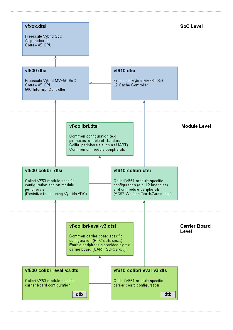
A device tree for a custom carrier board can also implement this extra dtsi for the common nodes between Colibri VF50/VF61. If the carrier board will only use Colibri VF50 or only Colibri VF61 anyway, the nodes of the common device tree file (vf-colibri-eval-v3.dtsi) can also be included in the main carrier board device tree (e.g. vf500-colibri-eval-v3.dts).
The Vybrid default boot scripts in U-Boot load the device tree file by combining multiple environment variables:${soc}-colibri-${fdt_board}.dtb. The soc environment variable is detected according to the module type the boot loader runs on (vf500/vf610). The fdt_board is a static environment variable set to eval-v3 by default. If you provide your own carrier board device tree, you can make use of this environment variable to select the correct device tree:
setenv fdt_board mycarriersaveenv
Pinmux (Vybrid)
Pin configurations such as pinmux or drive strength settings are defined by the pinctrl-vf610 driver. The base device tree vfxxx.dtsi defines the base configuration and allows these entries to be extended through theiomuxc label.
To configure a pin, a device tree node with the property fsl,pins is required. Cells need to be assigned to the property, each pin requires 5 cells. However, the first four are usually given by a pre-processor macro (seearch/arm/boot/dts/vf610-pinfunc.h), only the last cell need to be provided. This last cell contains the pin settings in a hexadecimal notation.
pinctrl_additionalgpio: additionalgpios { fsl,pins = < VF610_PAD_PTA17__GPIO_7 0x22ed >;};The bitwise definition for the last cell is given by the registers of Vybrids Input/Output Multiplexer Controller.
01 - Medium (100 MHz)
10 - Medium (100 MHz)
11 - High (200 MHz) 11SRE0 - Slow Slew Rate
1 - Fast Slew Rate 10ODE0 - Output is CMOS
1 - Output is open drain 9HYS0 - CMOS input
1 - Schmitt trigger input 8-6DSE000 - output driver disabled
001 - 150 Ohm (240 Ohm if pad is DDR)
010 - 75 Ohm (120 Ohm if pad is DDR)
011 - 50 Ohm (80 Ohm if pad is DDR)
100 - 37 Ohm 60 hm if pad is DDR)
101 - 30 Ohm (48 Ohm if pad is DDR)
110 - 25 Ohm
111 - 20 Ohm (34 Ohm if pad is DDR) 5-4PUS00 - 100 kOhm Pull Down
01 - 47 kOhm Pull Up
10 - 100 kOhm Pull Up
11 - 22 kOhm Pull Up 3PKE0 - Pull/Keeper Disabled
1 - Pull/Keeper Enabled Enableenable keeper or pull up/down function2PUE0 - Keeper enable
1 - Pull enableSelection between keeper and pull up/down function1OBE0 - Output buffer disabled
1 - Output buffer enabled 0IBE0 - Input buffer disabled
1 - Input buffer enabled
For further details see Chapter 4.2 of the Colibri VFxx data sheet or/and Chapter 6 of the NXP®/Freescale Vybrid reference manual.
GPIO (Vybrid)
On Vybrid almost all pins can be used as a GPIO. To be able to use a pin as a GPIO, a valid GPIO pinmux must be present in the device tree. Our default device tree contains such a pinmux entry for all pins which are defined being a GPIO by default (refer to the datasheet). For the other pins, make sure no driver is requesting them and create a proper pinmux configuration according to thePinmux chapter.
Kernel-space
Some drivers require a GPIO to be specified. A GPIO specification needs a reference to a GPIO node and one or more arguments. The amount of arguments is driver specific, for the Vybrid GPIO driver two cells ("arguments") are required. This is defined in the #gpio-cells property in the bindings of the GPIO driver (see vfxxx.dtsi). The binding documentation Documentation/devicetree/bindings/gpio/gpio-vf610.txt also specifies the meaning of those cells:
- #gpio-cells : Should be two. The first cell is the pin number and the second cell is used to specify the gpio polarity: 0 = active high 1 = active low
There are 5 GPIO ports on Vybrid, represented by the node references gpio0 through gpio4. Each of which can address up to 32 GPIOs. Which GPIO port is used is defined by the GPIO node reference, the GPIO number within the port is the first cell. The assignment of the to Colibri pins to the GPIO blocks/numbers can be found in the Colibri VFxx Datasheet, Chapter 4.4 List Functions, GPIO port column. The GPIO polarity cell need to be chosen according to the drivers/electronics needs. There are also preprocessor macros which can be used instead of the numbers (GPIO_ACTIVE_HIGH/GPIO_ACTIVE_LOW).
E.g. to reference the pin Colibri SO-DIMM 133 (according to the Colibri VFxx Datasheet connected to Vybrids PORT2[24]) one needs to use this GPIO specification:
gpios = <&gpio2 24 GPIO_ACTIVE_HIGH>
User-space
To use a SO-DIMM as GPIO using the sysfs interface (see GPIO (Linux)), a valid pinmux configuration is required. Most GPIOs have a valid configuration in the vf-colibri.dtsi device tree under the nodeadditionalgpios.
If there is no pinmux for the pin in question, the sysfs layer will respond with a "Invalid argument" error:
# echo 0 > /sys/class/gpio/export-sh: echo: write error: Invalid argument
In this case, add an Pinmux entry as described above.
In case the pin is already in use by a different driver, the error code would be "Device or resource busy".
# echo 42 > /sys/class/gpio/export -sh: echo: write error: Device or resource busy
Make sure the SO-DIMM pin in question is not in use by any driver. In case a driver is referencing it, you can disable the driver.
NXP®/Freescale iMX6
The modules Colibri iMX6S/iMX6DL share the same device tree binary, so do the modules Apalis iMX6D/iMX6Q. Click on the box to see the current version of the respective device treee file.
Pinmux (iMX6)
Pin configuration such as pinmux or drive strength is either set by pinctrl-imx6dl or the pinctrl-imx6q driver. The SoC level device trees defines the base configuration and allows to extend entries through theiomuxc label.
To configure a pin, a device tree node with the property fsl,pins is required. Cells need to be assigned to the property, each pin requires 5 cells. However, the first four are usually given by a pre-processor macro (seearch/arm/boot/dts/imx6dl-pinfunc.h or imx6q-pinfunc.h respectively), only the last cell need to be provided. This last cell contains the pin settings in a hexadecimal notation.
pinctrl_additionalgpio: additionalgpios { fsl,pins = < MX6QDL_PAD_EIM_A24__GPIO5_IO04 0x1b0b0 >;};There are preprocessor define for commonly used default pin configurations (e.g. PAD_CTRL_HYS_PU).
The bitwise definition for the last cell is given by the registers of the i.MX6 Input/Output Multiplexer Controller.
1 - Schmitt trigger input 15-14PUS00 - 100 kOhm Pull Down
01 - 47 kOhm Pull Up
10 - 100 kOhm Pull Up
11 - 22 kOhm Pull Up 13PUE0 - Keeper enable
1 - Pull enableSelection between keeper and pull up/down function12PKE0 - Pull/Keeper Disabled
1 - Pull/Keeper Enabled Enableenable keeper or pull up/down function11ODE0 - Output is CMOS
1 - Output is open drain 7-6SPEED00 - Low (50 MHz)
01 - Medium (100,150 MHz)
10 - Medium (100,150 MHz)
11 - High (100,150,200 MHz) 5-3DSE000 - output driver disabled (Hi Z)
001 - 150 Ohm (240 Ohm if pad is DDR)
010 - 75 Ohm (120 Ohm if pad is DDR)
011 - 50 Ohm (80 Ohm if pad is DDR)
100 - 37 Ohm 60 hm if pad is DDR)
101 - 30 Ohm (48 Ohm if pad is DDR)
110 - 25 Ohm
111 - 20 Ohm (34 Ohm if pad is DDR) 0SRE0 - Slow Slew Rate
1 - Fast Slew Rate
For further details see Chapter 4 of the Toradex Colibri or Apalis iMX6 data sheet or/and Chapter 36 of the NXP®/Freescale i.MX6 application processor reference manual.
- Device Tree Customization (转)
- Device tree customization
- Customization
- Customization
- Customization
- Device Tree
- Device tree
- Device Tree
- Device Tree
- Device Tree
- Device Tree
- Device Tree
- device tree
- device tree
- Device Tree
- Device Tree
- device tree
- Device Tree
- Spring源码阅读 --BeanDefinition
- 互动教程 for Excel 2016
- stop subthread example with Event
- FusionCharts 3.2 使用说明 以及 swf
- 郑轻OJ 1205: 你爱我么?
- Device Tree Customization (转)
- 浅谈C#中常见的委托
- 完全卸载oracle11g步骤
- MySQL存储引擎engine=innodb和engine=myisam的区别
- java实现 阿拉伯数字转换为汉字数字 算法
- 线程同步--关键段CRITICAL_SECTION
- 纯代码的方式 通过storyboard文件创建 xib的方式创建
- 【项目问题总结】5:树形结构节点的级联删除逻辑
- VB.net学习笔记(二十五)Threading 命名空间