1-INTRODUCTION
来源:互联网 发布:centos 7 更改ftp目录 编辑:程序博客网 时间:2024/06/06 01:38
Please indicate the source: http://blog.csdn.net/gaoxiangnumber1
Welcome to my github: https://github.com/gaoxiangnumber1 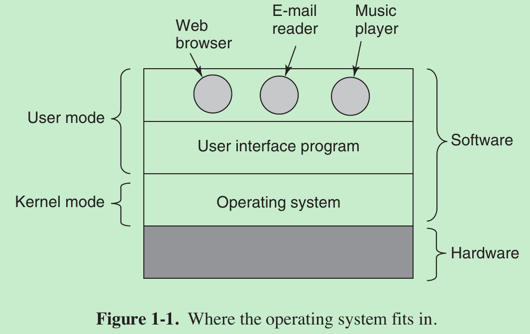
- The hardware consists of chips and similar physical objects. On top of the hardware is the software. Most computers have two modes of operation: kernel mode and user mode. The operating system, the most fundamental piece of software, runs in kernel mode (also called supervisor mode). In this mode it has complete access to all the hardware and can execute any instruction the machine is capable of executing. The rest of the software runs in user mode, in which only a subset of the machine instructions is available. Those instructions that affect control of the machine or do Input/Output are forbidden to user-mode programs.
- The user interface program, shell or GUI, is the lowest level of user-mode software, and allows the user to start other programs, such as a Web browser. These programs make heavy use of the operating system.
1.1 WHAT IS AN OPERATING SYSTEM?
1.1.1 The Operating System as an Extended Machine
- The job of the operating system is to create good abstractions and then implement and manage the abstract objects thus created. One of the major tasks of the operating system is to hide the hardware and present programs with nice, clean, elegant, consistent, abstractions to work with instead.
1.1.2 The Operating System as a Resource Manager
- The concept of an operating system as primarily providing abstractions to application programs is a top-down view. In the bottom-up view, the job of the operating system is to provide for an orderly and controlled allocation of the processors, memories, and I/O devices among the various programs wanting them.
- Resource management includes multiplexing (sharing) resources in two different ways: in time and in space.
- When a resource is time multiplexed, different programs or users take turns using it. First one of them gets to use the resource, then another, and so on. For example, with only one CPU and multiple programs that want to run on it, the operating system first allocates the CPU to one program, then another program gets to use the CPU, then another, and then eventually the first one again. Determining how the resource is time multiplexed — who goes next and for how long — is the task of the operating system.
- Space multiplexing. Each one gets part of the resource. For example, main memory is normally divided up among several running programs, so each one can be resident at the same time (for example, in order to take turns using the CPU). Assuming there is enough memory to hold multiple programs, it is more efficient to hold several programs in memory at once rather than give one of them all of it, especially if it only needs a small fraction of the total.
1.2 HISTORY OF OPERATING SYSTEMS
1.3 COMPUTER HARDWARE REVIEW
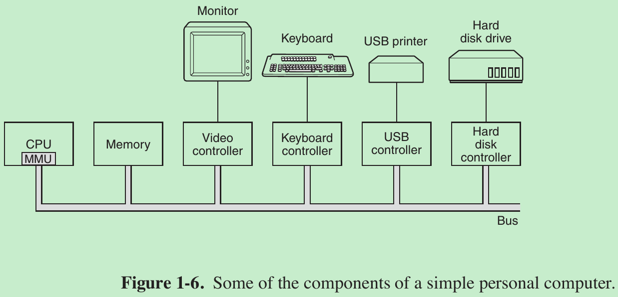
- The CPU, memory, and I/O devices are all connected by a system bus and communicate with one another over it.
1.3.1 Processors
- CPU fetches instructions from memory and executes them. The basic cycle of every CPU is to fetch the first instruction from memory, decode it to determine its type and operands, execute it, and then fetch, decode, and execute subsequent instructions. The cycle is repeated until the program finishes. In this way, programs are carried out.
- Each CPU has a specific set of instructions that it can execute. Thus an x86 processor cannot execute ARM programs and vice versa. Because accessing memory to get an instruction or data word takes much longer than executing an instruction, all CPUs contain some registers inside to hold key variables and temporary results.
- Program counter register: contains the memory address of the next instruction to be fetched. After that instruction has been fetched, the program counter is updated to point to its successor.
- Stack pointer register: points to the top of the current stack in memory. The stack contains one frame for each procedure that has been entered but not yet exited. A procedure’s stack frame holds those input parameters, local variables, and temporary variables that are not kept in registers.
- PSW (Program Status Word) register contains the condition code bits, which are set by comparison instructions, the CPU priority, the mode (user or kernel), and various other control bits. User programs may normally read the entire PSW but typically may write only some of its fields. The PSW plays an important role in system calls and I/O.
- The operating system must be fully aware of all the registers. When time multiplexing the CPU, the operating system will often stop the running program to (re)start another one. Every time it stops a running program, the operating system must save all the registers so they can be restored when the program runs later.
- Many modern CPUs have facilities for executing more than one instruction at the same time. For example, a CPU might have separate fetch, decode, and execute units, so that while it is executing instruction n, it could also be decoding instruction n + 1 and fetching instruction n + 2. Such an organization is called a pipeline and is illustrated in Fig. 1-7(a) for a pipeline with three stages.
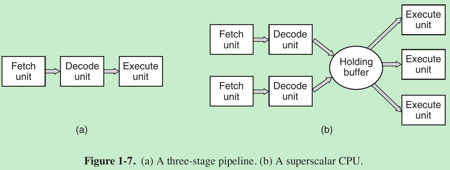
- In most pipeline designs, once an instruction has been fetched into the pipeline, it must be executed, even if the preceding instruction was a conditional branch that was not taken.
- Superscalar CPU, shown in Fig. 1-7(b). In this design, multiple execution units are present, for example, one for integer arithmetic, one for floating-point arithmetic, and one for Boolean operations. Two or more instructions are fetched at once, decoded, and dumped into a holding buffer until they can be executed. As soon as an execution unit becomes available, it looks in the holding buffer to see if there is an instruction it can handle, and if so, it removes the instruction from the buffer and executes it.
- Most CPUs (except very simple ones used in embedded systems) have two modes, kernel mode and user mode. Usually, a bit in the PSW (Program Status Word) controls the mode. When running in kernel mode, the CPU can execute every instruction in its instruction set and use every feature of the hardware. On desktop and server machines, the operating system normally runs in kernel mode, giving it access to the complete hardware. On most embedded systems, a small piece runs in kernel mode, with the rest of the operating system running in user mode.
- User programs always run in user mode, which permits only a subset of the instructions to be executed and a subset of the features to be accessed. Generally, all instructions involving I/O and memory protection are disallowed in user mode.
- Setting the PSW mode bit to enter kernel mode is also forbidden. To obtain services from the operating system, a user program must make a system call, which traps into the kernel and invokes the operating system. The TRAP instruction switches from user mode to kernel mode and starts the operating system. When the work has been completed, control is returned to the user program at the instruction following the system call.
- Computers have traps other than the instruction for executing a system call. Most of the other traps are caused by the hardware to warn of an exceptional situation such as an attempt to divide by 0 or a floating-point underflow. In all cases the operating system gets control and must decide what to do. Sometimes the program must be terminated with an error. Other times the error can be ignored. If the program has announced in advance that it wants to handle certain kinds of conditions, control can be passed back to the program to let it deal with the problem.
- A thread is a kind of lightweight process, which is a running program. Multithreading or hyperthreading: allow the CPU to hold the state of two different threads and then switch back and forth on a nanosecond time scale. Suppose one of the processes needs to read a word from memory (which takes many clock cycles), a multithreaded CPU can just switch to another thread. Multithreading does not offer true parallelism. Only one process at a time is running, but thread-switching time is reduced to the order of a nanosecond(纳秒).
- Each thread appears to the operating system as a separate CPU. Consider a system with two actual CPUs, each with two threads. The operating system will see this as four CPUs. If there is only enough work to keep two CPUs busy at a certain point in time, it may inadvertently schedule two threads on the same CPU, with the other CPU completely idle. This choice is far less efficient than using one thread on each CPU.
1.3.2 Memory
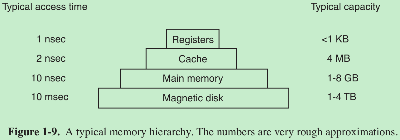
- The memory system is constructed as a hierarchy of layers, as shown in Fig. 1-9. The top layers have higher speed, smaller capacity, and greater cost per bit than the lower ones.
- First: The top layer consists of the registers internal to the CPU. They are made of the same material as the CPU and are as fast as the CPU. There is no delay in accessing them. The storage capacity available in them is typically 32 × 32 bits on a 32-bit CPU and 64 × 64 bits on a 64-bit CPU. Less than 1 KB in both cases. Programs must manage the registers (i.e., decide what to keep in them) themselves, in software.
- Second: Cache memory is mostly controlled by the hardware. Main memory is divided up into cache lines, typically 64 bytes, with addresses 0 to 63 in cache line 0, 64 to 127 in cache line 1, and so on. The most heavily used cache lines are kept in a high-speed cache located inside or very close to the CPU. When the program needs to read a memory word, the cache hardware checks to see if the line needed is in the cache. If it is, called a cache hit(高速缓存命中), the request is satisfied from the cache and no memory request is sent over the bus to the main memory. Cache hits normally take about two clock cycles. Cache misses have to go to memory, with a substantial time penalty. Cache memory is limited in size due to its high cost. Some machines have two or even three levels of cache, each one slower and bigger than the one before it.
- Caching plays a major role in many areas of computer science, not just caching lines of RAM. Whenever a resource can be divided into pieces, some of which are used much more heavily than others, caching is often used to improve performance. Operating systems use it all the time. For example, most operating systems keep heavily used files in main memory to avoid having to fetch them from the disk repeatedly.
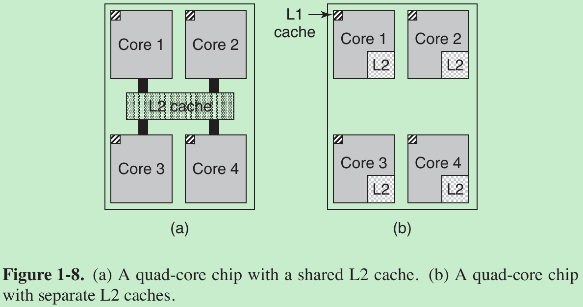
- Modern CPUs have two of caches.
- The first level or L1 cache is always inside the CPU and usually feeds decoded instructions into the CPU’s execution engine. Most chips have a second L1 cache for very heavily used data words. The L1 caches are typically 16 KB each.
- There is often a second cache, called the L2 cache, that holds several megabytes of recently used memory words.
- The difference between the L1 and L2 caches lies in the timing. Access to the L1 cache is done without any delay, whereas access to the L2 cache involves a delay of one or two clock cycles.
- Third: Main memory. This is the workhorse of the memory system. Main memory is usually called RAM (Random Access Memory). All CPU requests that cannot be satisfied out of the cache go to main memory.
- Many computers have a small amount of nonvolatile random-access memory. Unlike RAM, nonvolatile memory does not lose its contents when the power is switched off. ROM (Read Only Memory) is programmed at the factory and cannot be changed afterward. It is fast and inexpensive. The bootstrap loader used to start the computer and some I/O cards is contained in ROM.
- EEPROM (Electrically Erasable PROM) and flash memory are also nonvolatile, but in contrast to ROM can be erased and rewritten. Writing them takes orders of magnitude more time than writing RAM, so they are used in the same way ROM is, only with the additional feature that it is now possible to correct bugs in programs they hold by rewriting them in the field.
- Another kind of memory is CMOS, which is volatile. Many computers use CMOS memory to hold the current time and date. The CMOS memory and the clock circuit that increments the time in it are powered by a small battery, so the time is correctly updated, even when the computer is unplugged. The CMOS memory can also hold the configuration parameters, such as which disk to boot from. CMOS is used because it draws so little power that the original factory-installed battery often lasts for several years.
1.3.3 Disks
- Fourth: magnetic disk (hard disk). Disk storage is larger and cheaper, but is slower. The reason is that a disk is a mechanical device, as shown in Fig. 1-10.
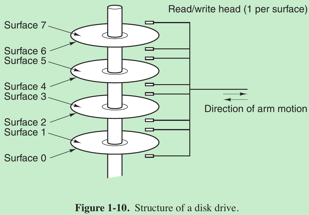
- Information is written onto the disk in a series of concentric circles. At any given arm position, each of the heads can read an annular region called a track. Together, all the tracks for a given arm position form a cylinder. Each track is divided into some number of sectors, typically 512 bytes per sector. On modern disks, the outer cylinders contain more sectors than the inner ones.
- Moving the arm from one cylinder to the next takes about 1 msec. Moving it to a random cylinder typically takes 5 to 10 msec, depending on the drive. Once the arm is on the correct track, the drive must wait for the needed sector to rotate under the head, an additional delay of 5 to 10 msec, depending on the drive’s RPM. Once the sector is under the head, reading or writing occurs at a rate of 50 MB/sec on low-end disks to 160 MB/sec on faster ones.
- Many computers support a scheme known as virtual memory. This scheme makes it possible to run programs larger than physical memory by placing them on the disk and using main memory as a kind of cache for the most heavily executed parts. This scheme requires remapping memory addresses on the fly to convert the address the program generated to the physical address in RAM where the word is located. This mapping is done by a part of the CPU called the MMU (Memory Management Unit).
1.3.4 I/O Devices
- I/O devices generally consist of two parts: a controller and the device itself. The controller is a chip or a set of chips that physically controls the device. It accepts commands from the operating system, for example, to read data from the device, and carries them out.
- The actual control of the device is complicated and detailed, so it is the job of the controller is to present a simpler interface to the operating system.
- Devices have fairly simple interfaces, both because they cannot do much and to make them standard. The latter is needed so that any SATA disk controller can handle any SATA disk, for example.
- SATA(串行高级技术附件Serial Advanced Technology Attachment ) is currently the standard type of disk on many computers. Since the actual device interface is hidden behind the controller, all that the operating system sees is the interface to the controller, which may be quite different from the interface to the device.
- Because each type of controller is different, different software is needed to control each one. The software that talks to a controller, giving it commands and accepting responses, is called a device driver. Each controller manufacturer has to supply a driver for each operating system it supports. Thus a scanner may come with drivers for OS X, Windows and Linux, for example.
- To be used, the driver has to be put into the operating system so it can run in kernel mode. Drivers can actually run outside the kernel, and operating systems like Linux and Windows nowadays do offer some support for doing so. The vast majority of the drivers still run below the kernel boundary.
- There are three ways the driver can be put into the kernel.
- The first way is to relink the kernel with the new driver and then reboot the system. Many older UNIX systems work like this.
- The second way is to make an entry in an operating system file telling it that it needs the driver and then reboot the system. At boot time, the operating system goes and finds the drivers it needs and loads them. Windows works this way.
- The third way is for the operating system to be able to accept new drivers while running and install them on the fly without the need to reboot. This way used to be rare but is becoming much more common now.
- Every controller has a small number of registers that are used to communicate with it. For example, a minimal disk controller might have registers for specifying the disk address, memory address, sector count, and direction (read or write). To activate the controller, the driver gets a command from the operating system, then translates it into the appropriate values to write into the device registers. The collection of all the device registers forms the I/O port space.
- On some computers, the device registers are mapped into the operating system’s address space (the addresses it can use), so they can be read and written like ordinary memory words. On such computers, no special I/O instructions are required and user programs can be kept away from the hardware by not putting these memory addresses within their reach (e.g., by using base and limit registers).
On other computers, the device registers are put in a special I/O port space, with each register having a port address. On these machines, special IN and OUT instructions are available in kernel mode to allow drivers to read and write the registers. - The former scheme eliminates the need for special I/O instructions but uses up some of the address space; the latter uses no address space but requires special instructions. Both systems are widely used.
Input and output can be done in three different ways. - User-Program issue a system call -> Kernel translates into a procedure call to the appropriate driver -> Driver start the I/O and sits in a tight loop continuously polling the device to see if it is done (usually there is some bit that indicates that the device is still busy). When the I/O has completed, the driver puts the data (if any) where they are needed and returns. The operating system then returns control to the caller.
This method is called busy waiting and has the disadvantage of binding the CPU polling the device until it is finished. - The second method is for the driver to start the device and ask it to give an interrupt when it is finished. At that point the driver returns. The operating system then blocks the caller if need be and looks for other work to do. When the controller detects the end of the transfer, it generates an interrupt to signal completion.
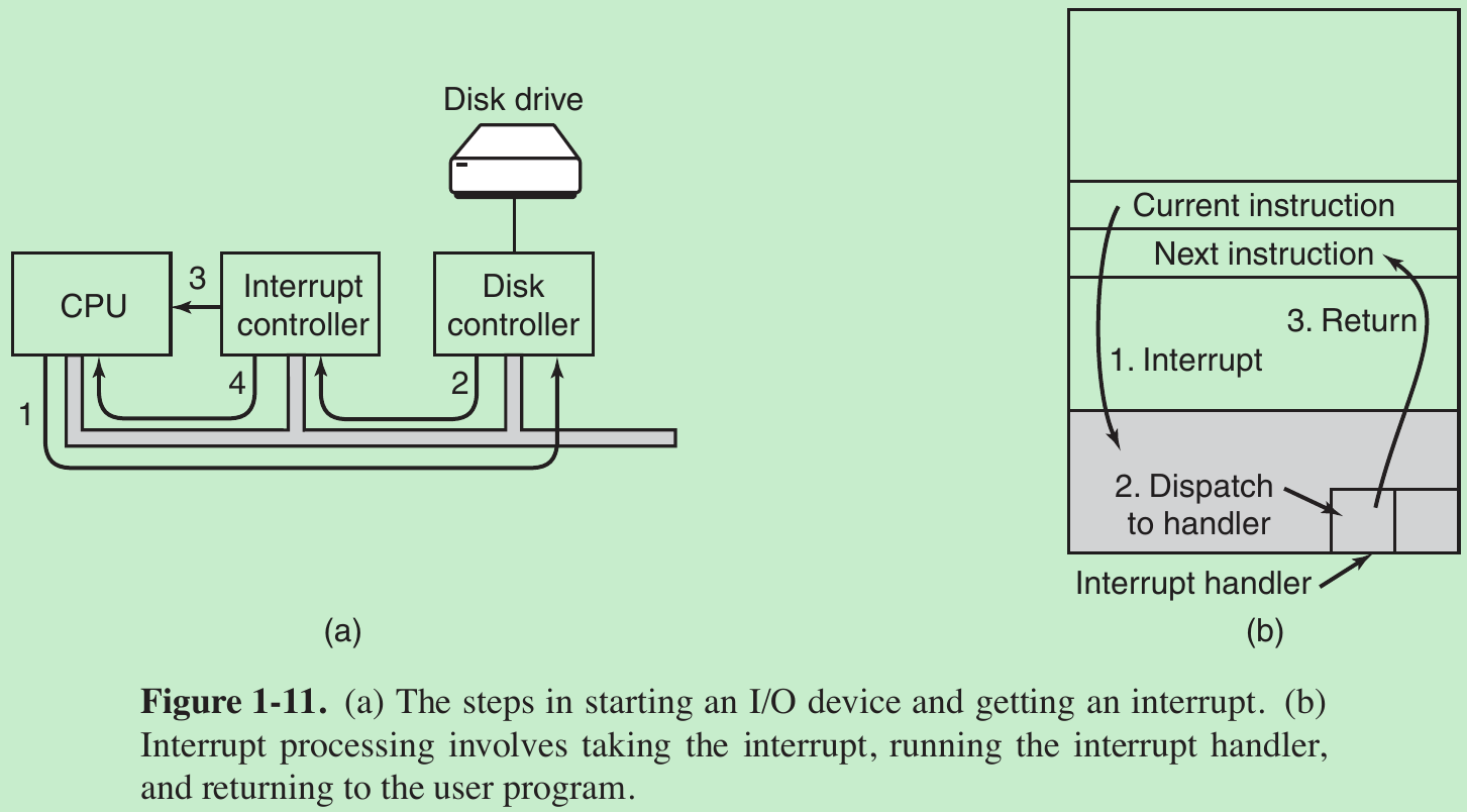
- In (a) we see a four-step process for I/O.
Step 1: The driver tells the controller what to do by writing into its device registers. The controller then starts the device.
Step 2: When the controller has finished reading or writing the number of bytes it has been told to transfer, it signals the interrupt controller chip using certain bus lines.
Step 3: If the interrupt controller is ready to accept the interrupt (which it may not be if it is busy handling a higher-priority one), it asserts a pin on the CPU chip telling it. Step 4: The interrupt controller puts the number of the device on the bus so the CPU can read it and know which device has just finished (many devices may be running at the same time). - Once the CPU has decided to take the interrupt, the program counter and PSW are typically then pushed onto the current stack and the CPU switched into kernel mode. The device number may be used as an index into part of memory to find the address of the interrupt handler for this device. This part of memory is called the interrupt vector. Once the interrupt handler (part of the driver for the interrupting device) has started, it removes the stacked program counter and PSW(program status word) and saves them, then queries the device to learn its status. When the handler is all finished, it returns to the previously running user program to the first instruction that was not yet executed.
- The third method for doing I/O makes use of special hardware: a DMA (Direct Memory Access) chip that can control the flow of bits between memory and some controller without constant CPU intervention. The CPU sets up the DMA chip, telling it how many bytes to transfer, the device and memory addresses involved, and the direction, and lets it go. When the DMA chip is done, it causes an interrupt, which is handled as described above.
- Interrupts can (and often do) happen at highly inconvenient moments, for example, while another interrupt handler is running. For this reason, the CPU has a way to disable interrupts and then reenable them later. While interrupts are disabled, any devices that finish continue to assert their interrupt signals, but the CPU is not interrupted until interrupts are enabled again. If multiple devices finish while interrupts are disabled, the interrupt controller decides which one to let through first, usually based on static priorities assigned to each device. The highest-priority device wins and gets to be serviced first. The others must wait.
1.3.5 Buses
- A large x86 system currently looks something like Fig. 1-12.
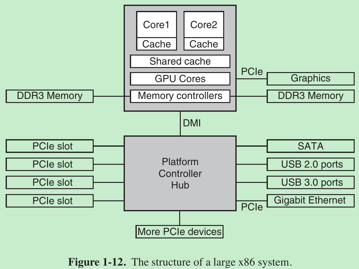
- This system has many buses (e.g., cache, memory, PCIe, PCI, USB, SATA, and DMI), each with a different transfer rate and function. The operating system must be aware of all of them for configuration and management. The main bus is the PCIe (总线和接口标准Peripheral Component Interconnect Express) bus.
- Capable of transferring tens of gigabits per second, PCIe is much faster than its predecessors. Before PCIe, most buses were shared and parallel.
- A shared bus architecture means that multiple devices use the same wires to transfer data. Thus, when multiple devices have data to send, you need determine who can use the bus. But PCIe makes use of dedicated, point-to-point connections.
- A parallel bus architecture used in traditional PCI means that you send each word of data over multiple wires. For instance, in regular PCI buses, a single 32-bit number is sent over 32 parallel wires. But PCIe uses a serial bus architecture and sends all bits in a message through a single connection, known as a lane. This is much simpler, because you do not have to ensure that all 32 bits arrive at the destination at exactly the same time. Parallelism is still used, because you can have multiple lanes in parallel. For instance, we may use 32 lanes to carry 32 messages in parallel.
- We still have many old devices for the older PCI standard. As we see in Fig. 1-12, these devices are hooked up to a separate hub processor.
- The CPU talks to memory over a fast DDR3 bus, to an external graphics device over PCIe and to all other devices via a hub over a DMI (Direct Media Interface) bus. The hub in turn connects all the other devices, using the Universal Serial Bus to talk to USB devices, the SATA bus to interact with hard disks and DVD drives, and PCIe to transfer Ethernet frames.
- Moreover, each of the CPU cores has a dedicated cache and a much larger cache that is shared between them. Each of these caches introduces another bus.
- The USB (Universal Serial Bus) was invented to attach all the slow I/O devices, such as the keyboard and mouse, to the computer. USB uses a small connector with four to eleven wires (depending on the version), some of which supply electrical power to the USB devices or connect to ground. USB is a centralized bus in which a root device polls all the I/O devices every 1 msec to see if they have any traffic. Any USB device can be connected to a computer and it will function immediately, without requiring a reboot.
- The SCSI (Small Computer System Interface) bus is a high-performance bus intended for fast disks, scanners, and other devices needing considerable bandwidth.
- To work in an environment such as that of Fig. 1-12, the operating system has to know what peripheral devices are connected to the computer and configure them. This requirement led Intel and Microsoft to design a PC system called plug and play.
- Before plug and play, each I/O card had a fixed interrupt request level and fixed addresses for its I/O registers. For example, the keyboard was interrupt 1 and used I/O addresses 0x60 to 0x64, and the printer was interrupt 7 and used I/O addresses 0x378 to 0x37A, and so on.
- The trouble came in when the user bought a sound card and a modem card and both happened to use, say, interrupt 4. They would conflict and would not work together. The solution was to include DIP switches or jumpers on every I/O card and instruct the user to set them to select an interrupt level and I/O device addresses that did not conflict with any others in the user’s system. However, this is very hard.
- What plug and play does is have the system automatically collect information about the I/O devices, centrally assign interrupt levels and I/O addresses, and then tell each card what its numbers are.
1.3.6 Booting the Computer
- Every PC contains a parentboard (motherboard). On the parentboard is a program called the system BIOS(Basic Input Output System). The BIOS contains low-level I/O software, including procedures to read the keyboard, write to the screen, and do disk I/O, among other things. Nowadays, it is held in a flash RAM, which is nonvolatile but which can be updated by the operating system when bugs are found in the BIOS.
- When the computer is booted, the BIOS is started. It first checks to see how much RAM is installed and whether the keyboard and other basic devices are installed and responding correctly. It starts out by scanning the PCIe and PCI buses to detect all the devices attached to them. If the devices present are different from when the system was last booted, the new devices are configured.
- The BIOS then determines the boot device by trying a list of devices stored in the CMOS memory. The user can change this list by entering a BIOS configuration program just after booting. Typically, an attempt is made to boot from a CD-ROM (or sometimes USB) drive, if one is present. If that fails, the system boots from the hard disk. The first sector from the boot device is read into memory and executed.
- This sector contains a program that normally examines the partition table at the end of the boot sector to determine which partition is active. Then a secondary boot loader is read in from that partition. This loader reads in the operating system from the active partition and starts it.
- The operating system then queries the BIOS to get the configuration information. For each device, it checks to see if it has the device driver. If not, it asks the user to insert a CD-ROM containing the driver or to download it from the Internet. Once it has all the device drivers, the operating system loads them into the kernel. Then it initializes its tables, creates whatever background processes are needed, and starts up a login program or GUI.
1.4 THE OPERATING SYSTEM ZOO
1.5 OPERATING SYSTEM CONCEPTS
1.5.1 Processes
- A process is basically a program in execution. Associated with each process is its address space, a list of memory locations from 0 to some maximum, which the process can read and write.
- The address space contains the executable program, the program’s data, and its stack. Also associated with each process is a set of resources, commonly including registers (including the program counter and stack pointer), a list of open files, lists of related processes, and all the other information needed to run the program. A process is fundamentally a container that holds all the information needed to run a program.
- Suppose we have (at least) three active processes: the video editor, the Web browser, and the email receiver. Periodically, the operating system decides to stop running one process and start running another, perhaps because the first one has used up more than its share of CPU time in the past second or two.
- When a process is suspended temporarily like this, it must later be restarted in exactly the same state it had when it was stopped. This means that all information about the process must be explicitly saved somewhere during the suspension. For example, the process may have several files open for reading at once. Associated with each of these files is a pointer giving the current position (i.e., the number of the byte or record to be read next). When a process is temporarily suspended, all these pointers must be saved so that a read call executed after the process is restarted will read the proper data. In many operating systems, all the information about each process, other than the contents of its own address space, is stored in an operating system table called the process table, which is an array of structures, one for each process currently in existence.
- Thus, a(suspended) process consists of its address space, usually called the core image, and its process table entry, which contains the contents of its registers and many other items needed to restart the process later.
- The key process-management system calls are those dealing with the creation and termination of processes. E.g.: A process called the command interpreter or shell reads commands from a terminal. The user has just typed a command requesting that a program be compiled. The shell must now create a new process that will run the compiler. When that process has finished the compilation, it executes a system call to terminate itself.
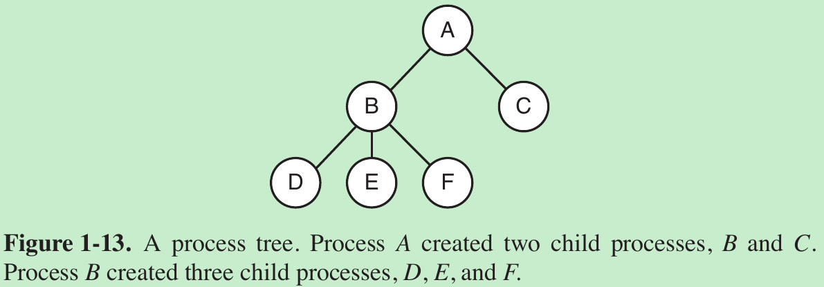
- If a process can create one or more other processes (referred to as child processes) and these processes in turn can create child processes, we quickly arrive at the process tree structure of Fig. 1-13. Related processes that are cooperating to get some job done often need to communicate with one another and synchronize their activities. This communication is called interprocess communication.
- Other process system calls are available to request more memory (or release unused memory), wait for a child process to terminate, and overlay its program with a different one.
- Sometimes there is a need to convey information to a running process that is not sitting around waiting for this information. For example, a process that is communicating with another process on a different computer does so by sending messages to the remote process over a computer network. To guard against the possibility that a message or its reply is lost, the sender may request that its own operating system notify it after a specified number of seconds, so that it can retransmit the message if no acknowledgement has been received yet. After setting this timer, the program may continue doing other work. When the specified number of seconds has elapsed, the operating system sends an alarm signal to the process. The signal causes the process to temporarily suspend whatever it was doing, save its registers on the stack, and start running a special signal-handling procedure, for example, to retransmit a possible lost message. When the signal handler is done, the running process is restarted in the state it was in just before the signal.
- Signals are the software analog of hardware interrupts and can be generated by a variety of causes in addition to timers expiring. Many traps detected by hardware, such as executing an illegal instruction or using an invalid address, are also converted into signals to the guilty process.
- Each person authorized to use a system is assigned a UID (User identification) by the system administrator. Every process started has the UID of the person who started it. A child process has the same UID as its parent. Users can be members of groups, each of which has a GID (Group identification).
- One UID, called the superuser (in UNIX), or Administrator (in Windows), has special power and may override many of the protection rules.
1.5.2 Address Spaces
- Every computer has some main memory that it uses to hold executing programs. Sophisticated operating systems allow multiple programs to be in memory at the same time. To keep them from interfering with one another (and with the operating system), some kind of protection mechanism is needed. While this mechanism has to be in the hardware, it is controlled by the operating system.
- Normally, each process has some set of addresses it can use, typically running from 0 up to some maximum. A technique called virtual memory exists, in which the operating system keeps part of the address space in main memory and part on disk and shuttles pieces back and forth between them as needed.
- In essence, the operating system creates the abstraction of an address space as the set of addresses a process may reference. The address space is decoupled from the machine’s physical memory and may be either larger or smaller than the physical memory.
1.5.3 Files
- System calls are needed to create files, remove files, read files, and write files. Before a file can be read, it must be located on the disk and opened, and after being read it should be closed, so calls are provided to do these things.
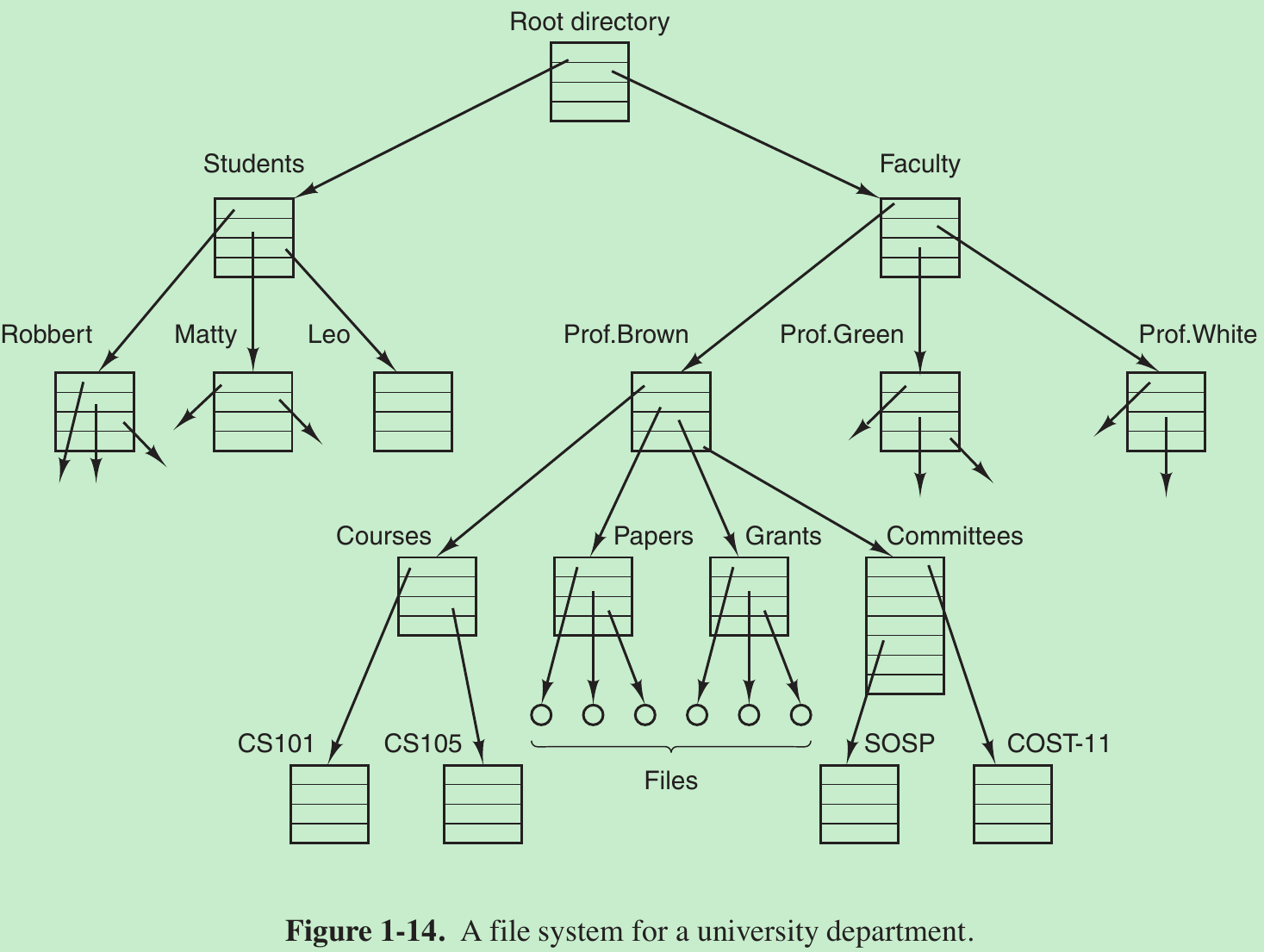
- To provide a place to keep files, most PC operating systems have the concept of a directory as a way of grouping files together. System calls are then needed to create and remove directories. Calls are also provided to put an existing file in a directory and to remove a file from a directory. Directory entries may be either files or other directories. This model gives rise to a hierarchy - the file system - as in Fig. 1-14.
- Before a file can be read or written, it must be opened, at which time the permissions are checked. If the access is permitted, the system returns a small integer called a file descriptor to use in subsequent operations. If the access is prohibited, an error code is returned.
- Another important concept in UNIX is the mounted file system. Most desktop computers have one or more optical drives into which DVDs can be inserted. They almost always have USB ports, into which USB memory sticks can be plugged, and some computers have floppy disks or external hard disks.
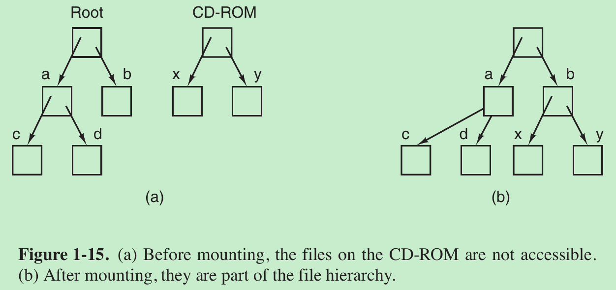
- To provide an elegant way to deal with these removable media, UNIX allows the file system on the optical disc to be attached to the main tree. The mount system call allows the file system on the CD-ROM to be attached to the root file system wherever the program wants it to be. In Fig. 1-15(b) the file system on the CD-ROM has been mounted on directory b, thus allowing access to files /b/x and /b/y. If a system contains multiple hard disks, they can all be mounted into a single tree as well.
- Another important concept in UNIX is the special file. Special files are provided in order to make I/O devices look like files. So they can be read and written using the same system calls as are used for reading and writing files.
- Two kinds of special files exist: block special files and character special files.
Block special files are used to model devices that consist of a collection of randomly addressable blocks, such as disks. By opening a block special file and reading, say, block 4, a program can directly access the fourth block on the device, without regard to the structure of the file system contained on it.
Character special files are used to model printers, modems, and other devices that accept or output a character stream. - By convention, the special files are kept in the /dev directory. For example, /dev/lp might be the printer (once called the line printer).
- A pipe is a sort of pseudofile that can be used to connect two processes, as shown in Fig. 1-16.
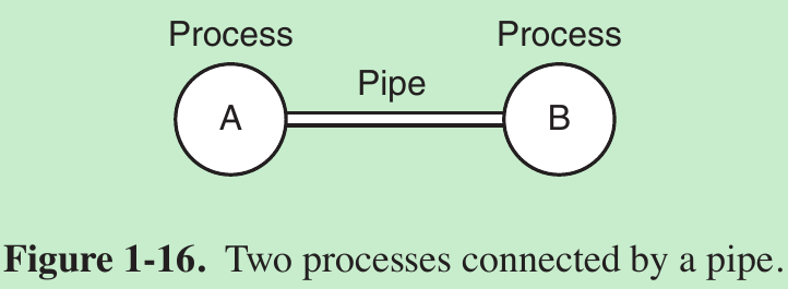
- If processes A and B wish to talk using a pipe, they must set it up in advance. When process A wants to send data to process B, it writes on the pipe as though it were an output file. In fact, the implementation of a pipe is very much like that of a file. Process B can read the data by reading from the pipe as though it were an input file. Thus, communication between processes in UNIX looks very much like ordinary file reads and writes.
1.5.4 Input/Output
- Every operating system has an I/O subsystem for managing its I/O devices. Some of the I/O software is device independent, that is, applies to many or all I/O devices equally well. Other parts of it, such as device drivers, are specific to particular I/O devices.
1.5.5 Protection
- Computers contain large amounts of information that users often want to protect and keep confidential. It is up to the operating system to manage the system security so that files, for example, are accessible only to authorized users.
1.5.6 The Shell
- Shell makes heavy use of many operating system features and thus serves as a good example of how the system calls are used. It is also the main interface between a user sitting at his terminal and the operating system.
- Many shells exist, including sh and bash. All of them support the functionality described below, which derives from the original shell (sh).
- When any user logs in, a shell is started up. The shell has the terminal as standard input and standard output. It starts out by typing the prompt, a character such as $, which tells the user that the shell is waiting to accept a command.
- If the user now types
$ date
the shell creates a child process and runs the date program as the child. While the child process is running, the shell waits for it to terminate. When the child finishes, the shell types the prompt again and tries to read the next input line.
1.5.7 Ontogeny Recapitulates Phylogeny
1.6 SYSTEM CALLS
- Operating systems have two main functions: providing abstractions to user programs and managing the computer’s resources. The interface between user programs and the operating system is primarily about dealing with the abstractions.
- Any single-CPU computer can execute only one instruction at a time. If a process is running a user program in user mode and needs a system service, it has to execute a trap instruction to transfer control to the operating system. The operating system then figures out what the calling process wants by inspecting the parameters. Then it carries out the system call and returns control to the instruction following the system call. Only system calls enter the kernel and procedure calls do not.
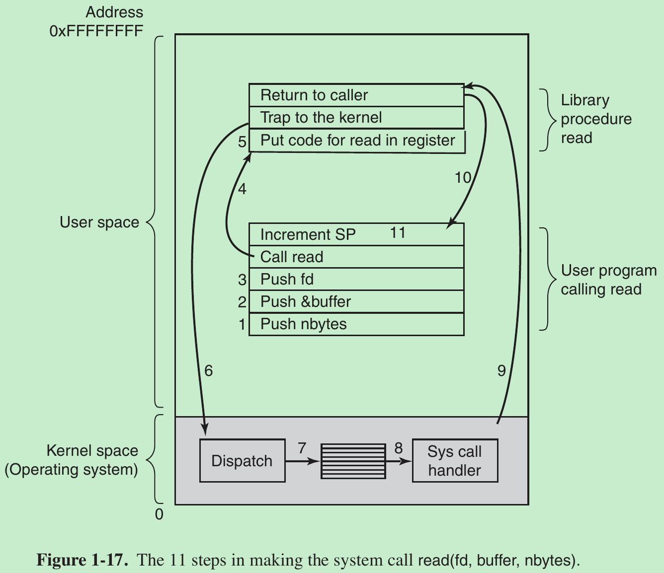
- System calls are performed in a series of steps. In preparation for calling the read library procedure, which actually makes the read system call, the calling program first pushes the parameters onto the stack, as shown in steps 1–3 in Fig. 1-17. Then comes the actual call to the library procedure (step 4). This instruction is the normal procedure-call instruction used to call all procedures.
- The library procedure typically puts the system-call number in a place where the operating system expects it, such as a register (step 5). Then it executes a TRAP instruction to switch from user mode to kernel mode and start execution at a fixed address within the kernel (step 6).
- The TRAP instruction is similar to the procedure-call instruction in the sense that the instruction following it is taken from a distant location and the return address is saved on the stack for use later.
- The TRAP instruction differs from the procedure-call instruction in two ways.
- First, it switches into kernel mode. The procedure call instruction does not change the mode.
- Second, rather than giving a relative or absolute address where the procedure is located, the TRAP instruction cannot jump to an arbitrary address. Depending on the architecture, either it jumps to a single fixed location or there is an 8-bit field in the instruction giving the index into a table in memory containing jump addresses, or equivalent.
- The kernel code that starts following the TRAP examines the system-call number and then dispatches to the correct system-call handler, usually via a table of pointers to system-call handlers indexed on system-call number (step 7). At that point the system-call handler runs (step 8). Once it has completed its work, control may be returned to the user-space library procedure at the instruction following the TRAP instruction (step 9). This procedure then returns to the user program in the usual way procedure calls return (step 10). To finish the job, the user program has to clean up the stack, as it does after any procedure call (step 11). Assuming the stack grows downward, the compiled code increments the stack pointer exactly enough to remove the parameters pushed before the call to read. The program is now free to do whatever it wants to do next.
- In step 9 above, we said ‘‘may be returned to the user-space library procedure’’ because the system call may block the caller, preventing it from continuing.
For example, if it is trying to read from the keyboard and nothing has been typed yet, the caller has to be blocked. In this case, the operating system will look around to see if some other process can be run next. Later, when the desired input is available, this process will get the attention of the system and run steps 9–11.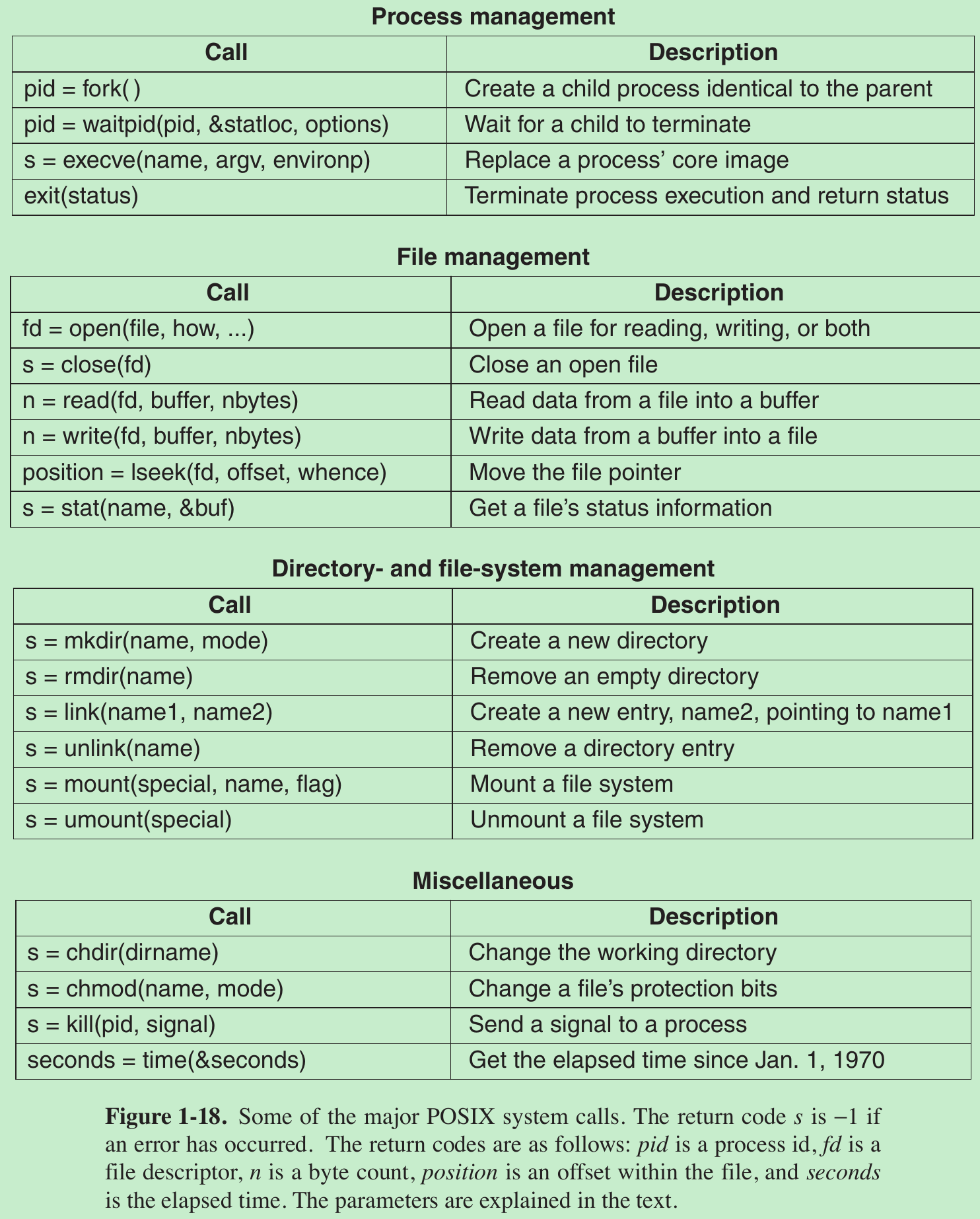
- POSIX has about 100 procedure calls. Some of the most important ones are listed in Fig. 1-18, grouped for convenience in four categories.
- The mapping of POSIX procedure calls onto system calls is not one-to-one. The POSIX standard specifies a number of procedures that a conformant system must supply, but it does not specify whether they are system calls, library calls, or something else. If a procedure can be carried out without invoking a system call (i.e., without trapping to the kernel), it will usually be done in user space for reasons of performance. But most of the POSIX procedures do invoke system calls, usually with one procedure mapping directly onto one system call. In a few cases, especially where several required procedures are only minor variations of one another, one system call handles more than one library call.
1.6.1 System Calls for Process Management
- Fork is the only way to create a new process in POSIX(Portable Operating System Interface可移植性操作系统接口). It creates an exact duplicate of the original process. After the fork, the original process(parent) and the copy (child) go their separate ways. All the variables have identical values at the time of the fork, but since the parent’s data are copied to create the child, subsequent changes in one of them do not affect the other one. The program text, which is unchangeable, is shared between parent and child. The fork call returns a value, which is zero in the child and equal to the child’s PID (Process identifier) in the parent. Using the returned PID, the two processes can see which one is the parent process and which one is the child process.
- Usually after a fork, the child will need to execute different code from the parent. Consider the case of the shell. It reads a command from the terminal, forks off a child process, waits for the child to execute the command, and then reads the next command when the child terminates. To wait for the child to finish, the parent executes a waitpid system call, which just waits until the child terminates (any child if more than one exists). Waitpid can wait for a specific child, or for any old child by setting the first parameter to −1. When waitpid completes, the address pointed to by the second parameter, statloc, will be set to the child process’ exit status (normal or abnormal termination and exit value).
- Consider how fork is used by the shell. When a command is typed, the shell forks off a new process. This child process must execute the user command. It does this by using the execve system call, which causes its entire core image to be replaced by the file named in its first parameter.
A simplified shell illustrating the use of fork, waitpid, and execve: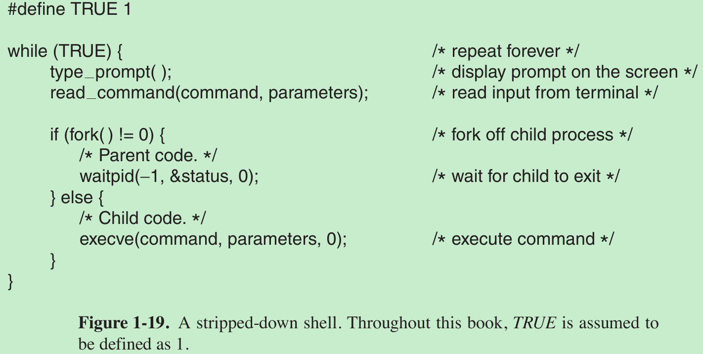
- In the most general case, execve has three parameters: the name of the file to be executed, a pointer to the argument array, and a pointer to the environment array. Various library routines are provided to allow the parameters to be omitted or specified in various ways.
- Consider the case of a command such as
cp file1 file2 - After the shell has forked, the child process locates and executes the file cp and passes to it the names of the source and target files. The main program of cp (and main program of most other C programs) contains the declaration main(argc, argv, envp).
- argc is a count of the number of items on the command line, including the program name. For the example above, argc is 3.
- argv is a pointer to an array. Element i of that array is a pointer to the ith string on the command line. In our example, argv[0] would point to the string ‘‘cp’’, argv[1] would point to the string ‘‘file1’’, and argv[2] would point to the string ‘‘file2’’.
- envp is a pointer to the environment, an array of strings containing assignments of the form name = value used to pass information such as the terminal type and home directory name to programs. In Fig. 1-19, no environment is passed to the child, so the third parameter of execve is a zero.
- exit, which processes should use when they are finished executing. It has one parameter, the exit status (0 to 255), which is returned to the parent via statloc in the waitpid system call.
- Processes in UNIX have their memory divided up into three segments: the text segment (i.e., the program code), the data segment (i.e., the variables), and the stack segment. The data segment grows upward and the stack grows downward, as shown in Fig. 1-20.
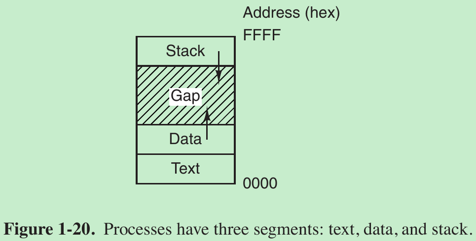
- Between them is a gap of unused address space. The stack grows into the gap automatically, as needed, but expansion of the data segment is done explicitly by using a system call, brk, which specifies the new address where the data segment is to end. This call is not defined by the POSIX standard, since programmers are encouraged to use the malloc library procedure for dynamically allocating storage, and the underlying implementation of malloc was not thought to be a suitable subject for standardization since few programmers use it directly and it is doubtful that anyone even notices that brk is not in POSIX.
1.6.2 System Calls for File Management
- To read or write a file, it must first be opened. This call specifies the file name to be opened, either as an absolute path name or relative to the working directory, as well as a code of O_RDONLY, O_WRONLY, or O_RDWR, meaning open for reading, writing, or both.
- To create a new file, the O_CREAT parameter is used. The file descriptor returned can then be used for reading or writing.
- The file can be closed by close, which makes the file descriptor available for reuse on a subsequent open.
- Associated with each file is a pointer that indicates the current position in the file. When reading (writing) sequentially, it normally points to the next byte to be read (written). The lseek call changes the value of the position pointer, so that subsequent calls to read or write can begin anywhere in the file.
- Lseek has three parameters: the first is the file descriptor for the file, the second is a file position, and the third tells whether the file position is relative to the beginning of the file, the current position, or the end of the file. The value returned by lseek is the absolute position in the file (in bytes) after changing the pointer.
- For each file, UNIX keeps track of the file mode (regular file, special file, directory, and so on), size, time of last modification, and other information. Programs can ask to see this information via the stat system call. The first parameter specifies the file to be inspected; the second one is a pointer to a structure where the information is to be put. The fstat calls does the same thing for an open file.
1.6.3 System Calls for Directory Management
- mkdir and rmdir create and remove empty directories, respectively.
- The next call is link. Its purpose is to allow the same file to appear under two or more names, often in different directories. A typical use is to allow several members of the same programming team to share a common file, with each of them having the file appear in his own directory, possibly under different names.
- Sharing a file is not the same as giving every team member a private copy; having a shared file means that changes that any member of the team makes are instantly visible to the other members—there is only one file. When copies are made of a file, subsequent changes made to one copy do not affect the others.
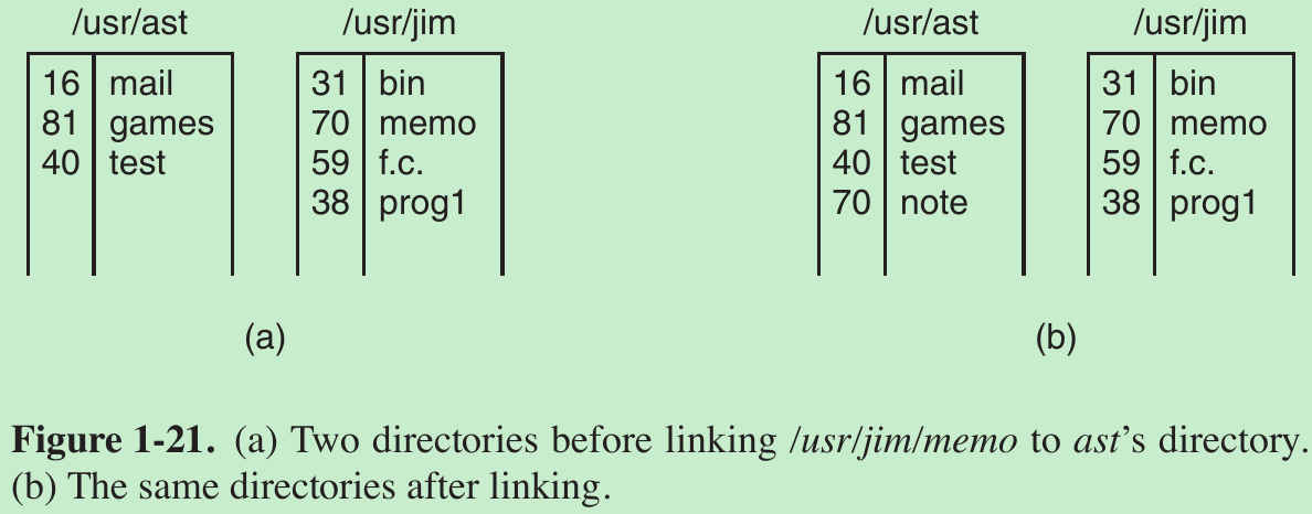
- To see how link works, consider the situation of Fig. 1-21(a). Here are two users, ast and jim, each having his own directory with some files. If ast now executes a program containing the system call link(“/usr/jim/memo”, “/usr/ast/note”);
the file memo in jim’s directory is now entered into ast’s directory under the name note. Thereafter, /usr/jim/memo and /usr/ast/note refer to the same file. - Every file in UNIX has a unique number, its i-number, that identifies it. This i-number is an index into a table of i-nodes, one per file, telling who owns the file, where its disk blocks are, and so on. A directory is simply a file containing a set of (i-number, ASCII name) pairs. In Fig. 1-21, mail has i-number 16, and so on.
- What link does is create a new directory entry with a (possibly new) name, using the i-number of an existing file. In Fig. 1-21(b), two entries have the same i-number (70) and thus refer to the same file. If either one is later removed, using the unlink system call, the other one remains. If both are removed, UNIX sees that no entries to the file exist (a field in the i-node keeps track of the number of directory entries pointing to the file), so the file is removed from the disk.
- By executing the mount system call, a USB file system can be attached to the root file system, as shown in Fig. 1-22.
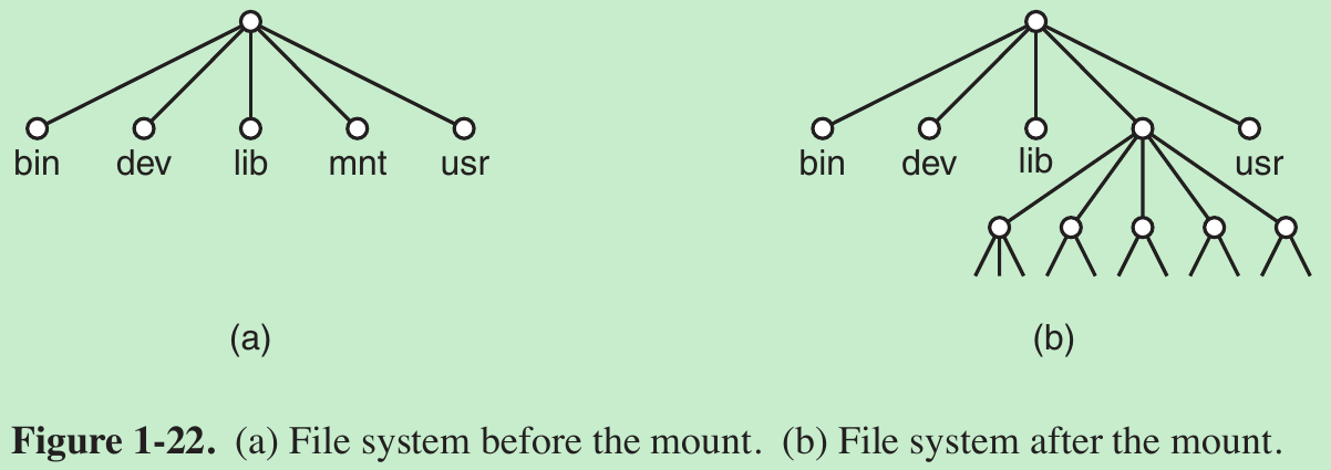
- A typical statement in C to mount is
mount(“/dev/sdb0”, “/mnt”, 0);
where the first parameter is the name of a block special file for USB drive 0, the second parameter is the place in the tree where it is to be mounted, and the third parameter tells whether the file system is to be mounted read-write or read-only. - When a file system is no longer needed, it can be unmounted with the umount system call.
1.6.4 Miscellaneous System Calls
- The chdir call changes the current working directory. After the call chdir(“/usr/ast/test”); an open on the file xyz will open /usr/ast/test/xyz. The concept of a working directory eliminates the need for typing (long) absolute path names all the time.
- In UNIX every file has a mode used for protection. The mode includes the read-write-execute bits for the owner, group, and others. The chmod system call makes it possible to change the mode of a file. For example, to make a file read-only by everyone except the owner, one could execute
chmod(“file”, 0644); - The kill system call is the way users and user processes send signals. If a process is prepared to catch a particular signal, then when it arrives, a signal handler is run. If the process is not prepared to handle a signal, then its arrival kills the process (hence the name of the call).
1.6.5 The Windows Win32 API
1.7 OPERATING SYSTEM STRUCTURE
1.8 THE WORLD ACCORDING TO C
1.9 RESEARCH ON OPERATING SYSTEMS
1.10 OUTLINE OF THE REST OF THIS BOOK
1.11 METRIC UNITS
1.12 SUMMARY
Please indicate the source: http://blog.csdn.net/gaoxiangnumber1
Welcome to my github: https://github.com/gaoxiangnumber1
0 0
- 1 Introduction
- 1 introduction
- 1、introduction
- (1)Introduction
- 1-Introduction
- 1-INTRODUCTION
- 1- Introduction
- [suykens] 1 Introduction
- HMM学习(1)-introduction
- Design Pattern:1 introduction
- WCF Introduction (1)
- introduction u-boot(1)
- Introduction to JAXB (1)
- CMake Introduction 1
- Makefile 学习(1):Introduction
- Shell scripting 1 - introduction
- !!!Chapter 1 Introduction
- !!!Chapter 1 Introduction
- Oracle【BC】
- apicloud图片缓存的使用和查看清除缓存
- JavaScript闭包的理解
- 补: Codeforces Round #355 (Div. 2)
- 1094. The Largest Generation
- 1-INTRODUCTION
- python2.7+opencv3.1 打开摄像头
- 367. Valid Perfect Square
- MYSQL索引:对聚簇索引和非聚簇索引的认识
- Spring初级学习!!!
- System V和Posix消息队列的差别
- Spark DataFrame中的join类型
- Devstack 多节点自动化部署
- GSON的使用介绍