3-MEMORY MANAGEMENT
来源:互联网 发布:黑马云计算大数据视频 编辑:程序博客网 时间:2024/06/07 05:42
Please indicate the source: http://blog.csdn.net/gaoxiangnumber1
Welcome to my github: https://github.com/gaoxiangnumber1
- The part of the operating system that manages (part of) the memory hierarchy is called the memory manager. Its job is to efficiently manage memory: keep track of which parts of memory are in use, allocate memory to processes when they need it, and deallocate it when they are done.
3.1 NO MEMORY ABSTRACTION
- The simplest memory abstraction is to have no abstraction at all. Every program saw the physical memory. When a program executed an instruction like
MOV REGISTER1, 1000
the computer moved the contents of physical memory location 1000 to REGISTER1. The model of memory presented to the programmer was a set of addresses from 0 to some maximum, each address corresponding to a cell containing some number of bits, commonly eight. - Under these conditions, it was not possible to have two running programs in memory at the same time. If the first program wrote a new value to, say, location 2000, this would erase whatever value the second program was storing there.
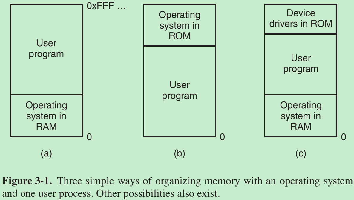
- When the system is organized in this way, generally only one process at a time can be running. As soon as the user types a command, the operating system copies the requested program from disk to memory and executes it. When the process finishes, the operating system displays a prompt character and waits for a user new command. When the operating system receives the command, it loads a new program into memory, overwriting the first one.
Running Multiple Programs Without a Memory Abstraction
- What the operating system has to do is save the entire contents of memory to a disk file, then bring in and run the next program. As long as there is only one program at a time in memory, there are no conflicts.
- With the addition of some special hardware, it is possible to run multiple programs concurrently without swapping. Memory was divided into 2-KB blocks and each was assigned a 4-bit protection key held in special registers inside the CPU. The PSW (Program Status Word) also contained a 4-bit key. The hardware trapped any attempt by a running process to access memory with a protection code different from the PSW key. Since only the operating system could change the protection keys, user processes were prevented from interfering with one another and with the operating system itself.

- This solution had a major drawback depicted in Fig. 3-2. Here we have two programs, each 16 KB in size, as shown in Fig. 3-2(a) and (b). The former is shaded to indicate that it has a different memory key than the latter. The first program starts out by jumping to address 24, which contains a MOV instruction. The second program starts out by jumping to address 28, which contains a CMP instruction.
- When the two programs are loaded consecutively in memory starting at address 0, we have the situation of Fig. 3-2(c).
- After the programs are loaded, they can be run. Since they have different memory keys, neither one can damage the other. When the first program starts, it executes the JMP 24 instruction. This program functions normally. However, the operating system may decide to run the second program, which has been loaded above the first one, at address 16,384. The first instruction executed is JMP 28, which jumps to the ADD instruction in the first program, instead of the CMP instruction it is supposed to jump to. The program will most likely crash in well under 1 sec.
- The problem here is that the two programs both reference absolute physical memory. What we want is that each program can reference a private set of addresses local to it.
- Solution: When a program was loaded at address 16,384, the constant 16,384 was added to every program address during the load process (so ‘‘JMP 28’’ became ‘‘JMP 16,412’’, etc.). While this mechanism works if done right, it is slows down loading.
3.2 A MEMORY ABSTRACTION: ADDRESS SPACES
3.2.1 The Notion of an Address Space
- Two problems have to be solved to allow multiple applications to be in memory at the same time without interfering with each other: protection and relocation.
- As the process concept creates a kind of abstract CPU to run programs, the address space creates a kind of abstract memory for programs to live in. An address space is the set of addresses that a process can use to address memory. Each process has its own address space, independent of those belonging to other processes (except in some special circumstances where processes want to share their address spaces).
- How to give each program its own address space, so address 28 in one program means a different physical location than address 28 in another program?
Base and Limit Registers
- What it does is map each process’ address space onto a different part of physical memory in a simple way. The classical solution is to equip each CPU with two special hardware registers, usually called the base and limit registers. When these registers are used, programs are loaded into consecutive memory locations wherever there is room and without relocation during loading, as shown in Fig. 3-2(c).
- When a process is run, the base register is loaded with the physical address where its program begins in memory and the limit register is loaded with the length of the program. In Fig. 3-2(c), the base and limit values that would be loaded into these hardware registers when the first program is run are 0 and 16,384, respectively. The values used when the second program is run are 16,384 and 32,768, respectively.
- Every time a process references memory, either to fetch an instruction or read or write a data word, the CPU hardware automatically adds the base value to the address generated by the process before sending the address out on the memory bus. Simultaneously, it checks whether the address offered is equal to or greater than the value in the limit register, in which case a fault is generated and the access is aborted.
- A disadvantage of relocation using base and limit registers is the need to perform an addition and a comparison on every memory reference.
3.2.2 Swapping
- Keeping all processes in memory all the time requires a huge amount of memory and cannot be done if there is insufficient memory.
Two general approaches to dealing with memory overload
- First strategy: Swapping, which consists of bringing in each process in its entirety, running it for a while, then putting it back on the disk. Idle processes are mostly stored on disk, so they do not take up any memory when they are not running (although some of them wake up periodically to do their work, then go to sleep again).
- Second strategy: virtual memory, allows programs to run even when they are only partially in main memory.
Swapping
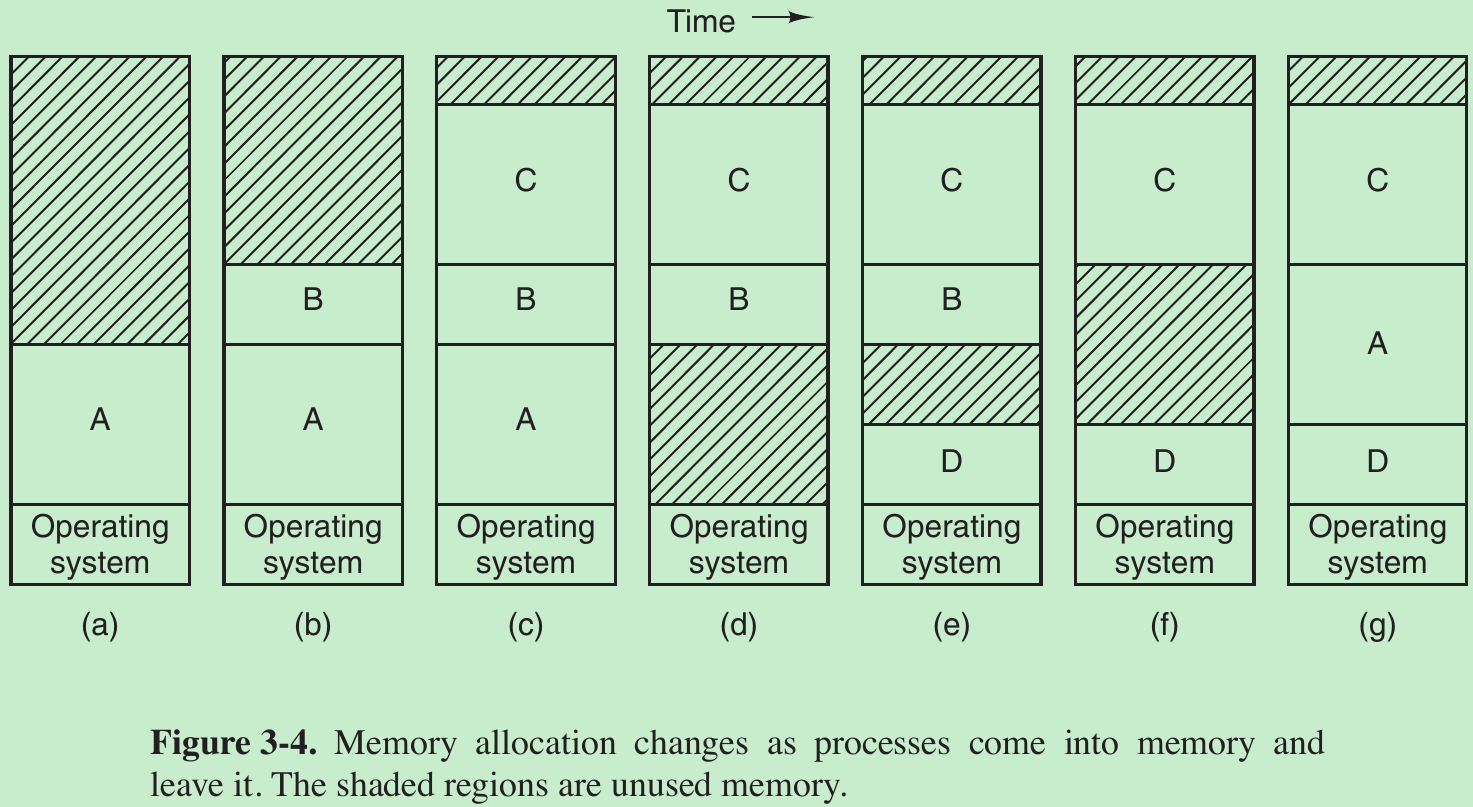
- Initially, only process A is in memory. Then processes B and C are created or swapped in from disk. In Fig. 3-4(d) A is swapped out to disk. Then D comes in and B goes out. Finally A comes in again. Since A is now at a different location, addresses contained in it must be relocated.
- When swapping creates multiple holes in memory, it is possible to combine them all into one big one by moving all the processes downward as far as possible. This technique is known as memory compaction. It is usually not done because it requires a lot of CPU time.
How much memory should be allocated for a process when created or swapped in?
- One strategy: processes are created with a fixed size that never changes. However, a problem occurs whenever a process tries to grow. If a hole is adjacent to the process, it can be allocated and the process allowed to grow into the hole. If the process is adjacent to another process, the growing process will either have to be moved to a hole in memory large enough for it, or one or more processes will have to be swapped out to create a large enough hole. If a process cannot grow in memory and the swap area on the disk is full, the process will have to suspended until some space is freed up (or it can be killed).
- It is a good idea to allocate a little extra memory whenever a process is swapped in or moved, to reduce the overhead associated with moving or swapping processes that no longer fit in their allocated memory. However, when swapping processes to disk, only the memory actually in use should be swapped; it is wasteful to swap the extra memory as well.
3.2.3 Managing Free Memory
- There are two ways to keep track of memory usage: bitmaps and free lists. In Chapter 10, some specific memory allocators used in Linux (like buddy and slab allocators).
Bitmaps
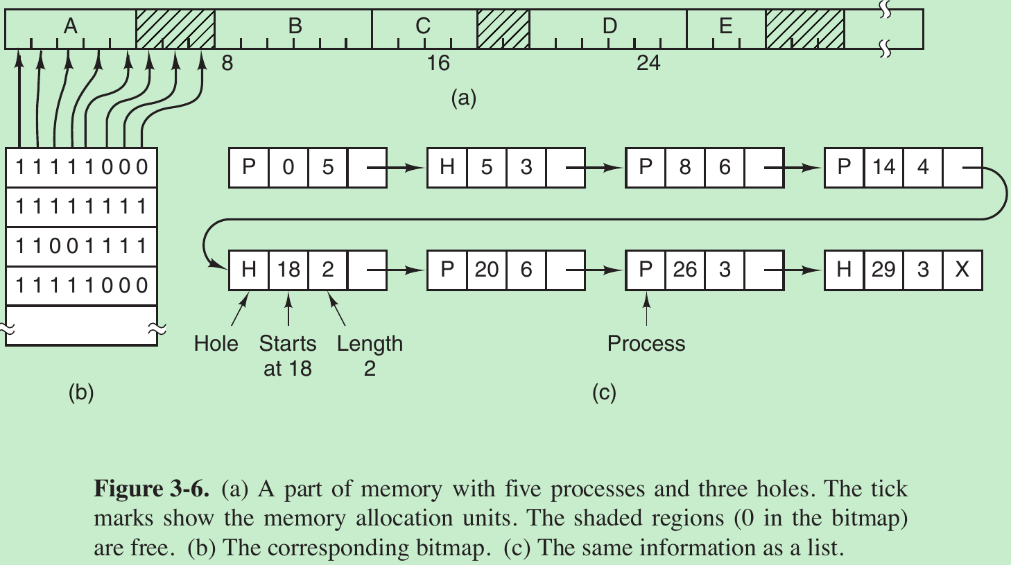
- With a bitmap, memory is divided into allocation units as small as a few words and as large as several kilobytes. Corresponding to each allocation unit is a bit in the bitmap, which is 0 if the unit is free and 1 if it is occupied (or vice versa).
- The size of the allocation unit is an important design issue. The smaller the allocation unit, the larger the bitmap. If the allocation unit is chosen large, the bitmap will be smaller, but appreciable memory may be wasted in the last unit of the process if the process size is not an exact multiple of the allocation unit.
- Bitmap is simple because the size of the bitmap depends only on the size of memory and the size of the allocation unit. The main problem is that when it has been decided to bring a k-unit process into memory, the memory manager must search the bitmap to find a run of k consecutive 0 bits in the map. Searching a bitmap for a run of a given length is a slow operation; this is an argument against bitmaps.
Linked Lists
- Maintain a linked list of allocated and free memory segments, where a segment either contains a process or is an empty hole between two processes.
- Each entry in the list specifies a hole (H) or process (P), the address at which it starts, the length, and a pointer to the next item. In this example, the segment list is kept sorted by address. Sorting this way has the advantage that when a process terminates or is swapped out, updating the list is straightforward.
- A terminating process normally has two neighbors (except when it is at the very top or bottom of memory). These may be either processes or holes, leading to the four combinations shown in Fig. 3-7.

- Since the process table slot for the terminating process will normally point to the list entry for the process itself, it may be more convenient to have the list as a double-linked list. This structure makes it easier to find the previous entry and to see if a merge is possible.
- When the processes and holes are kept on a list sorted by address, several algorithms can be used to allocate memory for a created process (or an existing process being swapped in from disk). We assume that the memory manager knows how much memory to allocate.
- First fit.
The memory manager scans along the list of segments until it finds a hole that is big enough. The hole is then broken up into two pieces, one for the process and one for the unused memory, except the case of an exact fit. First fit is a fast algorithm because it searches as little as possible. - Next fit.
It works the same way as first fit, except that it keeps track of where it is whenever it finds a suitable hole. The next time it is called to find a hole, it starts searching the list from the place where it left off last time, instead of always at the beginning, as first fit does. - Best fit.
Best fit searches the entire list, from beginning to end, and takes the smallest hole that is adequate. Rather than breaking up a big hole that might be needed later, best fit tries to find a hole that is close to the actual size needed, to best match the request and the available holes.
Best fit is slower than first fit because it must search the entire list every time it is called. It also results in more wasted memory than first fit or next fit because it tends to fill up memory with tiny, useless holes. First fit generates larger holes on the average. - Worst fit.
Always take the largest available hole, so that the new hole will be big enough to be useful.
- First fit.
- All four algorithms can be speeded up by maintaining separate lists for processes and holes. All of them devote to inspecting holes, not processes. The disadvantage is the additional complexity and slowdown when deallocating memory, since a freed segment has to be removed from the process list and inserted into the hole list.
- If distinct lists are maintained for processes and holes, the hole list may be kept sorted on size, to make best fit faster. When best fit searches a list of holes from smallest to largest, as soon as it finds a hole that fits, it knows that the hole is the smallest one that will do the job, hence the best fit. With a hole list sorted by size, first fit and best fit are equally fast, and next fit is pointless.
- Quick fit, which maintains separate lists for some of the more common sizes requested.
For example, it might have a table with n entries, in which the first entry is a pointer to the head of a list of 4-KB holes, the second entry is a pointer to a list of 8-KB holes, the third entry a pointer to 12-KB holes, and so on. Holes of, say, 21 KB, could be put either on the 20-KB list or on a special list of odd-sized holes.
- Quick fit, which maintains separate lists for some of the more common sizes requested.
- With quick fit, finding a hole of the required size is extremely fast, but it has the same disadvantage as all schemes that sort by hole size, namely, when a process terminates or is swapped out, finding its neighbors to see if a merge with them is possible is quite expensive. If merging is not done, memory will quickly fragment into a large number of small holes into which no processes fit.
3.3 VIRTUAL MEMORY
- The basic idea behind virtual memory is that each program has its own address space, which is broken up into chunks called pages. Each page is a contiguous range of addresses. These pages are mapped onto physical memory, but not all pages have to be in physical memory at the same time to run the program.
- When the program references a part of its address space that is in physical memory, the hardware performs the necessary mapping on the fly. When the program references a part of its address space that is not in physical memory, the operating system is alerted to go get the missing piece and re-execute the instruction that failed.
- Virtual memory works just fine in a multiprogramming system, with bits and pieces of many programs in memory at once. While a program is waiting for pieces of itself to be read in, the CPU can be given to another process.
3.3.1 Paging
- When a program executes an instruction like
MOV REG, 1000
it does so to copy the contents of memory address 1000 to REG (or vice versa). - These program-generated addresses are called virtual addresses and form the virtual address space.
- On computers without virtual memory, the virtual address is put directly onto the memory bus and causes the physical memory word with the same address to be read or written.
- When virtual memory is used, the virtual addresses do not go directly to the memory bus. Instead, they go to an MMU (Memory Management Unit) that maps the virtual addresses onto the physical memory addresses, as illustrated in Fig. 3-8.

- In this example, the computer generates 16-bit addresses, from 0 up to 64K − 1. These are the virtual addresses. This computer has 32 KB of physical memory. So although 64-KB programs can be written, they cannot be loaded into memory in their entirety and run. A complete copy of a program’s core image, up to 64 KB, must be present on the disk, so that pieces can be brought in as needed.
- The virtual address space consists of fixed-size units called pages. The corresponding units in the physical memory are called page frames. The pages and page frames are generally the same size. In this example they are 4 KB, but page sizes from 512 bytes to a gigabyte have been used in real systems.
- Transfers between RAM and disk are always in whole pages. Many processors support multiple page sizes that can be mixed and matched as the operating system sees fit. For instance, the x86-64 architecture supports 4-KB, 2-MB, and 1-GB pages, so we could use 4-KB pages for user applications and a single 1-GB page for the kernel.
- When the program tries to access address 0, for example, using the instruction
MOV REG, 0
virtual address 0 is sent to the MMU. The MMU sees that this virtual address falls in page 0 (0 to 4095), which according to its mapping is page frame 2 (8192 to 12287). It thus transforms the address to 8192 and outputs address 8192 onto the bus. The memory knows nothing about the MMU and just sees a request for reading or writing address 8192, which it honors. Thus, the MMU has effectively mapped all virtual addresses between 0 and 4095 onto physical addresses 8192 to 12287. - In the actual hardware, a Present/absent bit keeps track of which pages are physically present in memory.
- What happens if the program references an unmapped address, for example, by using the instruction
MOV REG, 32780
which is byte 12 within virtual page 8 (starting at 32768). - The MMU notices that the page is unmapped and causes the CPU to trap to the operating system. This trap is called a page fault. The operating system picks a little-used page frame and writes its contents back to the disk if it is not already there. It then fetches from the disk the page that was just referenced into the page frame just freed, changes the map, and restarts the trapped instruction.

- For example, if the operating system decided to evict page frame 1, it would load virtual page 8 at physical address 4096 and make two changes to the MMU map. First, it would mark virtual page 1’s entry as unmapped, to trap any future accesses to virtual addresses between 4096 and 8191. Second it would replace the cross in virtual page 8’s entry with a 1, so that when the trapped instruction is re-executed, it will map virtual address 32780 to physical address 4108 (4096 + 12).

- In Fig. 3-10 a virtual address, 8196 (00100000000001002), being mapped using the MMU map of Fig. 3-9. The incoming 16-bit virtual address is split into a 4-bit page number and a 12-bit offset.
- The page number is used as an index into the page table, yielding the number of the page frame corresponding to that virtual page.
- If the Present/absent bit is 0, a trap to the operating system is caused. If the bit is 1, the page frame number found in the page table is copied to the high-order 3 bits of the output register, along with the 12-bit offset, which is copied from the incoming virtual address. Together they form a 15-bit physical address. The output register is then put onto the memory bus as the physical memory address.
3.3.2 Page Tables
- The mapping of virtual addresses onto physical addresses can be summarized as follows:
- The virtual address is split into a virtual page number (high-order bits) and an offset (low-order bits).
- The virtual page number is used as an index into the page table to find the entry for that virtual page.
- From the page table entry, the page frame number (if any) is found.
- The page frame number is attached to the high-order end of the offset, replacing the virtual page number, to form a physical address that can be sent to the memory.
Structure of a Page Table Entry
- The exact layout of an entry in the page table is machine dependent, but the information is roughly the same from machine to machine. The size varies from computer to computer, but 32 bits is a common size.
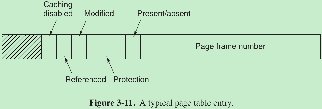
- Caching disabled bit: allows caching to be disabled for the page. This feature is important for pages that map onto device registers rather than memory. If the operating system is sitting in a tight loop waiting for some I/O device to respond to a command it was just given, it is essential that the hardware keep fetching the word from the device, and not use an old cached copy. With this bit, caching can be turned off. Machines that have a separate I/O space and do not use memory-mapped I/O do not need this bit.
- The Referenced bit is set whenever a page is referenced, either for reading or for writing. Its value is used to help the operating system choose a page to evict when a page fault occurs. Pages that are not being used are far better candidates than pages that are, and this bit plays an important role in several of the page replacement algorithms.
- When a page is written to, the hardware sets the Modified bit. This bit is of value when the operating system decides to reclaim a page frame. If the page in it has been modified (dirty), it must be written back to the disk. If it has not been modified (clean), it can be abandoned, since the disk copy is still valid. The bit is called the dirty bit, since it reflects the page’s state.
- The Protection bits tell what kinds of access are permitted. An arrangement is having 3 bits, one bit each for enabling reading, writing, and executing the page.
- Present/absent bit.
If this bit is 1, the entry is valid and can be used. If it is 0, the virtual page to which the entry belongs is not currently in memory. Accessing a page table entry with this bit set to 0 causes a page fault.
- The disk address used to hold the page when it is not in memory is not part of the page table. The page table holds only that information the hardware needs to translate a virtual address to a physical address. Information the operating system needs to handle page faults is kept in software tables inside the operating system. The hardware does not need it.
3.3.3 Speeding Up Paging
- In any paging system, two major issues must be faced:
1.The mapping from virtual address to physical address must be fast.
2.If the virtual address space is large, the page table will be large. - The second point follows from the fact that all modern computers use virtual addresses of at least 32 bits. With, say, a 4-KB page size, a 32-bit address space has 1 million pages. With 1 million pages in the virtual address space, the page table must have 1 million entries. And each process needs its own page table because it has its own virtual address space.
- The simplest design is to have a single page table consisting of an array of fast hardware registers, with one entry for each virtual page, indexed by virtual page number, as shown in Fig. 3-10.
- When a process is started up, the operating system loads the registers with the process’ page table, taken from a copy kept in main memory. During process execution, no more memory references are needed for the page table. The advantages are that it is straightforward and requires no memory references during mapping. A disadvantage is that it is unbearably expensive if the page table is large; it is just not practical most of the time. Another one is that having to load the full page table at every context switch would completely kill performance.
- At the other extreme, the page table can be entirely in main memory. All the hardware needs then is a single register that points to the start of the page table. This design allows the virtual-to-physical map to be changed at a context switch by reloading one register. It has the disadvantage of requiring one or more memory references to read page table entries during the execution of each instruction, making it very slow.
Translation Lookaside Buffers
- The starting point of most optimization techniques is that the page table is in memory. This design has an impact on performance. Consider a 1-byte instruction that copies one register to another. In the absence of paging, this instruction makes only one memory reference, to fetch the instruction. With paging, at least one additional memory reference will be needed, to access the page table. Since execution speed is generally limited by the rate at which the CPU can get instructions and data out of the memory, having to make two memory references per memory reference reduces performance by half. Under these conditions, no one would use paging.
- The solution is to equip computers with a small hardware device for mapping virtual addresses to physical addresses without going through the page table. The device, called a TLB (Translation Lookaside Buffer) or sometimes an associative memory.

- It is usually inside the MMU and consists of a small number of entries, eight in this example, but rarely more than 256. Each entry contains information about one page.
How the TLB functions.
- When a virtual address is presented to the MMU for translation, the hardware first checks to see if its virtual page number is present in the TLB by comparing it to all the entries in parallel. If a valid match is found and the access does not violate the protection bits, the page frame is taken directly from the TLB, without going to the page table. If the virtual page number is present in the TLB but the instruction is trying to write on a read-only page, a protection fault is generated.
- When the virtual page number is not in the TLB, the MMU detects the miss and does an ordinary page table lookup. It then evicts one of the entries from the TLB and replaces it with the page table entry just looked up. Thus if that page is used again soon, the second time it will result in a TLB hit rather than a miss. When an entry is cleared from the TLB, the modified bit is copied back into the page table entry in memory. The other values are already there, except the reference bit. When the TLB is loaded from the page table, all the fields are taken from memory.
Software TLB Management
- Up until now, we have assumed that every machine with paged virtual memory has page tables recognized by the hardware, plus a TLB. In this design, TLB management and handling TLB faults are done entirely by the MMU hardware. Traps to the operating system occur only when a page is not in memory.
- However, many RISC machines do nearly all of this page management in software. On these machines, the TLB entries are explicitly loaded by the operating system. When a TLB miss occurs, instead of the MMU going to the page tables to find and fetch the needed page reference, it just generates a TLB fault and tosses the problem into the lap of the operating system. The system must find the page, remove an entry from the TLB, enter the new one, and restart the instruction that faulted. And all of this must be done in a handful of instructions because TLB misses occur much more frequently than page faults.
- If the TLB is large (say, 64 entries) to reduce the miss rate, software management of the TLB turns out to be acceptably efficient. The main gain is a much simpler MMU, which frees up a considerable amount of area on the CPU chip for caches and other features that can improve performance.
- Various strategies were developed to improve performance on machines that do TLB management in software.
- To reduce TLB misses, the operating system can use its intuition to figure out which pages are likely to be used next and to pre-load entries for them in the TLB.
For example, when a client process sends a message to a server process on the same machine, it is likely that the server will have to run soon. So while processing the trap to do the send, the system can also check to see where the server’s code, data, and stack pages are and map them in before they get a chance to cause TLB faults. - The normal way to process a TLB miss, whether in hardware or in software, is to go to the page table and perform the indexing operations to locate the page referenced. The problem with doing this search in software is that the pages holding the page table may not be in the TLB, which will cause additional TLB faults during the processing. These faults can be reduced by maintaining a large (e.g., 4-KB) software cache of TLB entries in a fixed location whose page is always kept in the TLB. By first checking the software cache, the operating system can substantially reduce TLB misses.
- When software TLB management is used, it is essential to understand the difference between different kinds of misses.
- A soft miss occurs when the page referenced is not in the TLB, but is in memory.
All needed is for the TLB to be updated. No disk I/O is needed. Typically a soft miss takes 10–20 machine instructions to handle and can be completed in a couple of nanoseconds. - A hard miss occurs when the page itself is not in memory.
A disk access is required to bring in the page, which can take several milliseconds, depending on the disk being used. A hard miss is a million times slower than a soft miss. Looking up the mapping in the page table hierarchy is known as a page table walk.
- A soft miss occurs when the page referenced is not in the TLB, but is in memory.
- Some misses are slightly softer (or slightly harder) than other misses. Suppose the page walk does not find the page in the process’ page table and the program thus incurs a page fault. There are three possibilities.
- First, the page may actually be in memory, but not in this process’ page table. For instance, the page may have been brought in from disk by another process. So we do not need to access the disk again, but merely map the page appropriately in the page tables. This is a pretty soft miss that is known as a minor page fault.
- Second, a major page fault occurs if the page needs to be brought in from disk.
- Third, the program simply accessed an invalid address and no mapping needs to be added in the TLB at all. So the operating system kills the program with a segmentation fault. Only in this case did the program do something wrong. All other cases are automatically fixed by the hardware and/or the operating system at the cost of some performance.
3.3.4 Page Tables for Large Memories
Multilevel Page Tables 
- In (a) we have a 32-bit virtual address that is partitioned into a 10-bit PT1 field, a 10-bit PT2 field, and a 12-bit Offset field. Since offsets are 12 bits, pages are 4 KB, and there are a total of 220 of them.
- Multilevel page table method avoids keeping all the page tables in memory all the time. In particular, those that are not needed should not be kept around.
Suppose a process needs 12 MBs: the bottom 4 MBs of memory for program text, the next 4 MBs for data, and the top 4 MBs for the stack. In between the top of the data and the bottom of the stack is a large hole that is not used. - In (b) we see how the two-level page table works. On the left we see the top-level page table, with 1024 entries, corresponding to the 10-bit PT1 field. When a virtual address is presented to the MMU, it first extracts the PT1 field and uses this value as an index into the top-level page table. Each of these 1024 entries in the top-level page table represents 4MB.
- The entry located by indexing into the top-level page table yields the address or the page frame number of a second-level page table. Entry 0 of the top-level page table points to the page table for the program text, entry 1 points to the page table for the data, and entry 1023 points to the page table for the stack. The other (shaded) entries are not used. The PT2 field is now used as an index into the selected second-level page table to find the page frame number for the page itself.
- Consider the 32-bit virtual address 0x00403004 (4,206,596 decimal), which is 12,292 bytes into the data. This virtual address corresponds to PT1 = 1, PT2 = 3, and Offset = 4.
- The MMU first uses PT1 to index into the top-level page table and obtain entry 1, which corresponds to addresses 4M to 8M − 1.
- It then uses PT2 to index into the second-level page table just found and extract entry 3, which corresponds to addresses 12288 to 16383 within its 4M chunk (i.e., absolute addresses 4,206,592 to 4,210,687).
- This entry contains the page frame number of the page containing virtual address 0x00403004. If that page is not in memory, the Present/absent bit in the page table entry will have the value zero, causing a page fault. If the page is present in memory, the page frame number taken from the second-level page table is combined with the offset (4) to construct the physical address. This address is put on the bus and sent to memory.
- The two-level page table system can be expanded to three, four, or more levels. Additional levels give more flexibility.
Inverted(倒转的) Page Tables
- An alternative to ever-increasing levels in a paging hierarchy is known as inverted page tables. There is one entry per page frame in real memory, rather than one entry per page of virtual address space.
For example, with 64-bit virtual addresses, a 4-KB page size, and 4 GB of RAM, an inverted page table requires only 220 (4GB / 4KB) entries. The entry keeps track of which (process, virtual page) is located in the page frame. - Although inverted page tables save space, they have a downside: virtual-to-physical translation becomes much harder. When process n references virtual page p, the hardware can no longer find the physical page by using p as an index into the page table. It must search the entire inverted page table for an entry (n, p). Furthermore, this search must be done on every memory reference, not just on page faults.
- The way out of this dilemma is to make use of the TLB. If the TLB can hold all of the heavily used pages, translation can happen just as fast as with regular page tables. On a TLB miss, the inverted page table has to be searched in software.
- One feasible way to accomplish this search is to have a hash table hashed on the virtual address. All the virtual pages currently in memory that have the same hash value are chained together, as shown in Fig. 3-14.

- If the hash table has as many slots as the machine has physical pages, the average chain will be only one entry long, greatly speeding up the mapping. Once the page frame number has been found, the new (virtual, physical) pair is entered into the TLB.
3.4 PAGE REPLACEMENT ALGORITHMS
- When a page fault occurs, the operating system has to choose a page to evict (remove from memory) to make room for the incoming page. If the page to be removed has been modified while in memory, it must be rewritten to the disk to bring the disk copy up to date.
- System performance is much better if a page that is not heavily used is chosen. If a heavily used page is removed, it will probably have to be brought back in quickly, resulting in extra overhead.
3.4.1 The Optimal Page Replacement Algorithm
- Best Page Replacement Algorithm(impossible to implement):
When a page fault occurs, some set of pages is in memory. One of these pages will be referenced on the very next instruction (the page containing that instruction). Other pages may not be referenced until 1000 or more instructions later. Each page can be labeled with the number of instructions that will be executed before that page is first referenced. The page with the highest label should be removed. If one page will not be used for 8 million instructions and another page will not be used for 6 million instructions, removing the former pushes the page fault that will fetch it back as far into the future as possible. - The problem is that at the time of the page fault, the operating system has no way of knowing when each of the pages will be referenced next.
- But by running a program on a simulator and keeping track of all page references, it is possible to implement optimal page replacement on the second run by using the page-reference information collected during the first run.
- This log of page references refers only to the one program just measured and then with only one specific input. The page replacement algorithm derived from it is thus specific to that one program and input data. Although this method is useful for evaluating page replacement algorithms, it is of no use in practical systems.
3.4.2 The Not Recently Used Page Replacement Algorithm
- Most computers with virtual memory have two status bits, R and M, associated with each page.
—R is set whenever the page is referenced (read or written).
—M is set when the page is written to (modified).
The bits are contained in each page table entry. - These bits must be updated on every memory reference, so they are set by the hardware. Once a bit has been set to 1, it stays 1 until the operating system resets it.
- If the hardware does not have these bits, they can be simulated using the operating system’s page fault and clock interrupt mechanisms:
When a process is started up, all of its page table entries are marked as not in memory. As soon as any page is referenced, a page fault will occur. The operating system then sets the R bit in its internal tables, changes the page table entry to point to the correct page, with mode READ ONLY, and restarts the instruction. If the page is subsequently modified, another page fault will occur, allowing the operating system to set the M bit and change the page’s mode to READ/WRITE. - NRU Page Replacement Algorithm:
When a process is started up, both page bits for all its pages are set to 0 by the operating system. Periodically (e.g., on each clock interrupt), the R bit is cleared, to distinguish pages that have not been referenced recently from those that have been. When a page fault occurs, the operating system inspects all the pages and divides them into four categories based on the current values of their R and M bits:
Class 0: not referenced, not modified.
Class 1: not referenced, modified.
Class 2: referenced, not modified.
Class 3: referenced, modified.
NRU removes a page at random from the lowest-numbered nonempty class. - Class 1 pages occur when a class 3 page has its R bit cleared by a clock interrupt. Clock interrupts do not clear the M bit because this information is needed to know whether the page has to be rewritten to disk or not. Clearing R but not M leads to a class 1 page.
- This algorithm’s idea is that it is better to remove a modified page that has not been referenced in at least one clock tick than a clean page that is in heavy use.
- The main attraction of NRU is that it is efficient to implement, and gives a performance that may be adequate.
3.4.3 The First-In, First-Out (FIFO) Page Replacement Algorithm
- The operating system maintains a list of all pages currently in memory, with the most recent arrival at the tail and the least recent arrival at the head. On a page fault, the page at the head is removed and the new page added to the tail of the list.
- Because the oldest page may still be useful, FIFO is rarely used.
3.4.4 The Second-Chance Page Replacement Algorithm
- A modification to FIFO that avoids the problem of throwing out a heavily used page is to inspect the R bit of the oldest page.
- If R is 0, the page is both old and unused, so it is replaced immediately.
If R is 1, the bit is cleared, the page is put onto the end of the list of pages, and its load time is updated as though it had just arrived in memory. Then the search continues.
- Suppose that a page fault occurs at time 20. The oldest page is A, which arrived at time 0.
—If R = 0, it is evicted from memory, either by being written to the disk (dirty), or abandoned (clean).
—If R = 1, A is put onto the end of the list and its load time is reset to the current time (20). The R bit is cleared. The search for a suitable page continues with B. - What second chance is looking for is an old page that has not been referenced in the most recent clock interval. If all the pages have been referenced, second chance degenerates into pure FIFO.
- Imagine that all the pages in (a) have their R bits set. One by one, the operating system moves the pages to the end of the list, clearing the R bit each time it appends a page to the end of the list. Eventually, it comes back to page A, which now has its R bit cleared. At this point A is evicted. Thus the algorithm always terminates.
3.4.5 The Clock Page Replacement Algorithm
- Second chance is inefficient because it is constantly moving pages around on its list. A better approach is to keep all the page frames on a circular list in the form of a clock. The hand points to the oldest page.

- When a page fault occurs, the page being pointed to by the hand is inspected.
—R = 0, the page is evicted, the new page is inserted into the clock in its place, and the hand is advanced one position
—R = 1, it is cleared and the hand is advanced to the next page.
This process is repeated until a page is found with R = 0.
3.4.6 The Least Recently Used (LRU) Page Replacement Algorithm
- LRU(Least Recently Used) paging: When a page fault occurs, throw out the page that has been unused for the longest time.
- LRU is expensive to implement. To fully implement LRU, it is necessary to maintain a linked list of all pages in memory, with the most recently used page at the front and the least recently used page at the rear. The difficulty is that the list must be updated on every memory reference. Finding a page in the list, deleting it, and then moving it to the front is a time consuming operation.
- There are other ways to implement LRU with special hardware.
One method requires equipping the hardware with a 64-bit counter, C, that is automatically incremented after each instruction. Each page table entry must have a field large enough to contain the counter. After each memory reference, the current value of C is stored in the page table entry for the page just referenced. When a page fault occurs, the operating system examines all the counters in the page table to find the lowest one. That page is the least recently used.
3.4.7 Simulating LRU in Software: NFU (Not Frequently Used) algorithm
- Few machines have the required hardware, the NFU (Not Frequently Used) algorithm can be implemented in software.
- NFU uses a software counter associated with each page, initially zero. At each clock interrupt, the operating system scans all the pages in memory. For each page, the R bit is added to the counter. The counters roughly keep track of how often each page has been referenced. When a page fault occurs, the page with the lowest counter is chosen for replacement.
- The main problem with NFU is that it never forgets anything. For example, in a multipass compiler, pages that were heavily used during pass 1 still have a high count into later passes. In fact, if pass 1 happens to have the longest execution time of all the passes, the pages containing the code for subsequent passes may always have lower counts than the pass-1 pages. So the operating system will remove useful pages instead of pages no longer in use.
- A modification to NFU makes it able to simulate LRU quite well. The modification has two parts.
- The counters are each shifted right 1 bit before the R bit is added in.
- The R bit is added to the leftmost rather than the rightmost bit.

- Suppose that after the first clock tick the R bits for pages 0 to 5 have the values 1, 0, 1, 0, 1, and 1, respectively. After the six corresponding counters have been shifted and the R bit inserted at the left, they have the values shown in Fig. 3-17(a). The four remaining columns show the six counters after the next four clock ticks.
- When a page fault occurs, the page whose counter is the lowest is removed.
- This algorithm differs from LRU in two important ways.
- Consider pages 3 and 5 in (e). Neither has been referenced for two clock ticks; both were referenced in the tick prior to that.
According to LRU, if a page must be replaced, we should choose one of these two. But we do not know which of them was referenced last in the interval between tick 1 and tick 2. By recording only 1 bit per time interval, we have now lost the ability to distinguish references early in the clock interval from those occurring later. So we remove page 3, because page 5 was also referenced two ticks earlier and page 3 was not. - The second difference between LRU and aging is that in aging the counters have a finite number of bits (8 bits in this example), which limits its past horizon.
Suppose that two pages each have a counter value of 0. All we can do is pick one of them at random. In reality, it may be that one of the pages was last referenced nine ticks ago and the other was last referenced 1000 ticks ago. We have no way of seeing that. In practice, 8 bits is generally enough if a clock tick is around 20 msec. If a page has not been referenced in 160 msec, it probably is not that important.
- Consider pages 3 and 5 in (e). Neither has been referenced for two clock ticks; both were referenced in the tick prior to that.
3.4.8 The Working Set Page Replacement Algorithm
- In the purest form of paging, processes are started up with none of their pages in memory. As soon as the CPU tries to fetch the first instruction, it gets a page fault, causing the operating system to bring in the page containing the first instruction. Other page faults for global variables and the stack usually follow quickly. After a while, the process has most of the pages it needs and settles down to run with relatively few page faults. This strategy is called demand paging because pages are loaded only on demand, not in advance.
- The set of pages that a process is currently using is its working set.
- If the entire working set is in memory, the process will run without causing many faults until it moves into another execution phase (e.g., the next pass of the compiler).
- If the available memory is too small to hold the entire working set, the process will cause many page faults and run slowly. A program causing page faults every few instructions is said to be thrashing.
- In a multiprogramming system, processes are often moved to disk (i.e., all their pages are removed from memory) to let others have a turn at the CPU. The question arises of what to do when a process is brought back in again. Technically, nothing need be done. The process will just cause page faults until its working set has been loaded. The problem is that having numerous page faults every time a process is loaded is slow, and it also wastes considerable CPU time.
- Therefore, many paging systems try to keep track of each process’ working set and make sure that it is in memory before letting the process run. This approach is called the working set model. It is designed to greatly reduce the page fault rate. Loading the pages before letting processes run is also called prepaging. Note that the working set changes over time.
- At any instant of time, t, there exists a set consisting of all the pages used by the k most recent memory references. This set, w(k, t), is the working set.
- Because the most recent references(k = 1) must have used all the pages used by the most recent references(k > 1), and possibly others, w(k, t) is a monotonically nondecreasing function of k.
- The limit of w(k, t) as k becomes large is finite because a program cannot reference more pages than its address space contains, and few programs will use every page. Figure 3-18 depicts the size of the working set as a function of k.

- Because the working set varies slowly with time, it is possible to make a reasonable guess as to which pages will be needed when the program is restarted on the basis of its working set when it was last stopped.
- Prepaging consists of loading these pages before resuming the process. To implement the working set model, it is necessary for the operating system to keep track of which pages are in the working set.
- Having this information also leads to a possible page replacement algorithm: when a page fault occurs, find a page not in the working set and evict it. So we need to know which pages are in the working set.
- By definition, the working set is the set of pages used in the k most recent memory references (some authors use the k most recent page references, but the choice is arbitrary). To implement any working set algorithm, some value of k must be chosen in advance. Then, after every memory reference, the set of pages used by the most recent k memory references is uniquely determined.
- One could imagine a shift register of length k, with every memory reference shifting the register left one position and inserting the most recently referenced page number on the right. The set of all k page numbers in the shift register would be the working set.
- In theory, at a page fault, the contents of the shift register could be read out and sorted. Duplicate pages could then be removed. The result would be the working set. But maintaining the shift register and processing it at a page fault would both be prohibitively expensive, so this technique is never used.
- Instead, one commonly used approximation is to drop the idea of counting back k memory references and use execution time instead.
- For example, instead of defining the working set as those pages used during the previous 10 million memory references, we can define it as the set of pages used during the past 100 msec of execution time. In practice, such a definition is just as good and much easier to work with.
- For each process, only its own execution time counts. Thus if a process starts running at time T and has had 40 msec of CPU time at real time T + 100 msec, for working set purposes its time is 40 msec.
- The amount of CPU time a process has actually used since it started is often called its current virtual time. With this approximation, the working set of a process is the set of pages it has referenced during the past τ seconds of virtual time.
- A page replacement algorithm based on the working set. The basic idea is to find a page that is not in the working set and evict it.
- Because only pages located in memory are considered as candidates for eviction, pages that are absent from memory are ignored by this algorithm.
- Each entry contains (at least) two key items of information: the time the page was last used and the R (Referenced) bit. An empty white rectangle symbolizes the other fields not needed for this algorithm, such as the page frame number.

The algorithm works as follows.
- The hardware is assumed to set the R and M bits. A periodic clock interrupt is assumed to cause software to run that clears the Referenced bit on every clock tick.
- On every page fault, the page table is scanned to look for a suitable page to evict. As each entry is processed, the R bit is examined.
- If R is 1, the current virtual time is written into the Time of last use field in the page table, indicating that the page was in use at the time the fault occurred. Since the page has been referenced during the current clock tick, it is in the working set and is not a candidate for removal ( τ is assumed to span multiple clock ticks).
- If R is 0, the page has not been referenced during the current clock tick and may be a candidate for removal. To see whether or not it should be removed, its age ( = current virtual time - Time of last use) is computed and compared to τ .
—If age > τ , the page is no longer in the working set and the new page replaces it. The scan continues updating the remaining entries.
—If age <= τ , the page is still in the working set. The page is temporarily spared, but the page with the greatest age (smallest value of Time of last use) is noted.
- If the entire table is scanned without finding a candidate to evict, that means that all pages are in the working set. In that case, if one or more pages with R = 0 were found, the one with the greatest age is evicted.
- In the worst case, all pages have been referenced during the current clock tick (and thus all have R = 1), so one is chosen at random for removal, preferably a clean page, if one exists.
3.4.9 The WSClock Page Replacement Algorithm
- The basic working set algorithm is slow since the entire page table has to be scanned at each page fault until a suitable candidate is located. An improved algorithm, which is based on the clock algorithm but also uses the working set information, is called WSClock. Due to its simplicity of implementation and good performance, it is widely used in practice.

- The data structure needed is a circular list of page frames. Initially, this list is empty. When the first page is loaded, it is added to the list. As more pages are added, they go into the list to form a ring. Each entry contains the Time of last use field from the basic working set algorithm, as well as the R bit (shown) and the M bit (not shown).
- At each page fault the page pointed to by the hand is examined first.
- If R = 1, the page has been used during the current tick so it is not an candidate to remove. Then the R bit is set to 0, the hand advanced to the next page, and the algorithm repeated for that page.
- If R = 0.
—If the age is greater than τ and the page is clean, it is not in the working set and a valid copy exists on the disk. The page frame is claimed and the new page put there, as shown in (d).
—If the page is dirty, it cannot be claimed immediately since no valid copy is present on disk. To avoid a process switch, the write to disk is scheduled, but the hand is advanced and the algorithm continues with the next page. After all, there might be an old, clean page further down the line that can be used immediately.
- In principle, all pages might be scheduled for disk I/O on one cycle around the clock. To reduce disk traffic, a limit might be set, allowing a maximum of n pages to be written back. Once this limit has been reached, no new writes would be scheduled.
- What happens if the hand comes all the way around and back to its starting point? There are two cases:
- At least one write has been scheduled.
The hand just keeps moving, looking for a clean page. Since one or more writes have been scheduled, eventually some write will complete and its page will be marked as clean. The first clean page encountered is evicted. This page is not necessarily the first write scheduled because the disk driver may reorder writes in order to optimize disk performance. - No writes have been scheduled.
All pages are in the working set. Lacking additional information, the simplest thing to do is claim any clean page and use it. The location of a clean page could be kept track of during the sweep. If no clean pages exist, then the current page is chosen as the victim and written back to disk.
- At least one write has been scheduled.
3.4.10 Summary of Page Replacement Algorithms

- The optimal algorithm evicts the page that will be referenced furthest in the future. There is no way to determine which page this is, so in practice this algorithm cannot be used. It is useful as a benchmark against which other algorithms can be measured.
- The NRU algorithm divides pages into four classes depending on the state of the R and M bits. A random page from the lowest-numbered class is chosen. This algorithm is easy to implement, but it is very crude. Better ones exist.
- FIFO keeps track of the order in which pages were loaded into memory by keeping them in a linked list. Removing the oldest page then becomes trivial, but that page might still be in use, so FIFO is a bad choice.
- Second chance is a modification to FIFO that checks if a page is in use before removing it. If it is, the page is spared. This modification improves the performance.
- Clock is a different implementation of second chance. It has the same performance properties, but takes a little less time to execute the algorithm.
- LRU is an excellent algorithm, but it cannot be implemented without special hardware.
- NFU is a crude attempt to approximate LRU. It is not very good.
- Aging is a much better approximation to LRU and can be implemented efficiently. It is a good choice.
- The working set algorithm gives reasonable performance, but it is somewhat expensive to implement.
- WSClock gives good performance and is efficient to implement.
- The two best algorithms are aging and WSClock. They are based on LRU and the working set, respectively. Both give good paging performance and can be implemented efficiently.
3.5 DESIGN ISSUES FOR PAGING SYSTEMS
3.5.1 Local versus Global Allocation Policies
- We have discussed several algorithms for choosing a page to replace when a fault occurs. A major issue associated with this choice is how memory should be allocated among the competing runnable processes.

- In (a), three processes, A, B, and C, make up the set of runnable processes. Suppose A gets a page fault. Should the page replacement algorithm try to find the least recently used page considering only the six pages currently allocated to A, or should it consider all the pages in memory?
- If it looks only at A’s pages, the page with the lowest age value is A5, so we get the situation of (b).
If the page with the lowest age value is removed without regard to whose page it is, page B3 will be chosen and we will get the situation of (c).
The algorithm of (b) is a local page replacement algorithm, whereas that of (c) is a global algorithm. - Local algorithms effectively correspond to allocating every process a fixed fraction of the memory. Global algorithms dynamically allocate page frames among the runnable processes. Thus the number of page frames assigned to each process varies in time.
- In general, global algorithms work better, especially when the working set size can vary a lot over the lifetime of a process. If a local algorithm is used and the working set grows, thrashing will result, even if there are a sufficient number of free page frames. If the working set shrinks, local algorithms waste memory.
- If a global algorithm is used, the system must continually decide how many page frames to assign to each process. One way is to monitor the working set size as indicated by the aging bits, but this approach does not necessarily prevent thrashing. The working set may change size in milliseconds, whereas the aging bits are a very crude measure spread over a number of clock ticks.
- Another approach is to have an algorithm for allocating page frames to processes. One way is to periodically determine the number of running processes and allocate each process an equal share. Suppose with 12416 available page frames and 10 processes, each process gets 1241 frames. The remaining six go into a pool to be used when page faults occur.
- Although this method may seem fair, it makes little sense to give equal shares of the memory to a 10 KB process and a 300 KB process. Instead, pages can be allocated in proportion to each process’ total size, with a 300 KB process getting 30 times the allotment of a 10 KB process. It is probably wise to give each process some minimum number, so that it can run no matter how small it is.
- If a global algorithm is used, it may be possible to start each process up with some number of pages proportional to the process’ size, but the allocation has to be updated dynamically as the processes run. One way to manage the allocation is to use the PFF (Page Fault Frequency) algorithm. It tells when to increase or decrease a process’ page allocation but says nothing about which page to replace on a fault. It just controls the size of the allocation set.
- For a large class of page replacement algorithms, it is known that the fault rate decreases as more pages are assigned. This is the assumption behind PFF, as is illustrated in Fig. 3-23.

- The dashed line marked A corresponds to a page fault rate that is unacceptably high, so the faulting process is given more page frames to reduce the fault rate.
- The dashed line marked B corresponds to a page fault rate so low that we can assume the process has too much memory. In this case, page frames may be taken away from it.
- PFF tries to keep the paging rate for each process within acceptable bounds.
- Some page replacement algorithms can work with either a local replacement policy or a global one. For example, FIFO can replace the oldest page in all of memory (global algorithm) or the oldest page owned by the current process (local algorithm). The choice of local versus global is independent of the algorithm in some cases.
- Other page replacement algorithms, only a local strategy makes sense. The working set and WSClock algorithms refer to specific process and must be applied in that context. There is no working set for the machine as a whole, and trying to use the union of all the working sets would lose the locality property and not work well.
3.5.2 Load Control
- Whenever the combined working sets of all processes exceed the capacity of memory, thrashing can be expected. One symptom of this situation is that the PFF algorithm indicates that some processes need more memory but no processes need less memory. So there is no way to give more memory to those processes needing it without hurting some other processes. The only solution is to temporarily get rid of some processes.
- A good way to reduce the number of processes competing for memory is to swap some of them to the disk and free up all the pages they are holding. For example, one process can be swapped to disk and its page frames divided up among other processes that are thrashing. If the thrashing stops, the system can run for a while this way. If it does not stop, another process has to be swapped out, and so on, until the thrashing stops. Thus even with paging, swapping may still be needed, only now swapping is used to reduce potential demand for memory, rather than to reclaim pages.
- Swapping processes out to decrease the load on memory is reminiscent of(令人回忆起) two-level scheduling, in which some processes are put on disk and a short-term scheduler is used to schedule the remaining processes. The two ideas can be combined, with just enough processes swapped out to make the page-fault rate acceptable. Periodically, some processes are brought in from disk and other ones are swapped out.
- Another factor to consider is the degree of multiprogramming. When the number of processes in main memory is too low, the CPU may be idle for substantial periods of time. This consideration argues for considering not only process size and paging rate when deciding which process to swap out, but also its characteristics, such as whether it is CPU bound or I/O bound, and what characteristics the remaining processes have.
3.5.3 Page Size
- The page size is a parameter that can be chosen by the operating system. Even if the hardware has been designed with, say, 4096-byte pages, the operating system can regard page pairs 0&1, 2&3, 4&5, and so on, as 8 KB pages by always allocating two consecutive 8192-byte page frames for them.
- Two factors argue for a small page size because a large page size will cause more wasted space to be in memory than a small page size.
- A randomly chosen text, data, or stack segment will not fill an integral number of pages. On the average, half of the final page will be empty. The extra space in that page is wasted. This wastage is called internal fragmentation. With n segments in memory and a page size of p bytes, n*p / 2 bytes will be wasted on internal fragmentation. This reasoning argues for a small page size.
- Consider a program consisting of eight sequential phases of 4 KB each. With a 32-KB page size, the program must be allocated 32 KB all the time. With a 16-KB page size, it needs only 16 KB. With a page size of 4 KB or smaller, it requires only 4 KB at any instant.
- On the other hand
- Small pages mean that programs will need many pages, and thus a large page table. A 32-KB program needs only four 8-KB pages, but 64 512-byte pages. Transfers to and from the disk are generally a page at a time, with most of the time being for the seek and rotational delay, so that transferring a small page takes almost as much time as transferring a large page. It might take 64 × 10 msec to load 64 512-byte pages, but only 4 × 12 msec to load four 8-KB pages.
- Small pages use up much valuable space in the TLB. Say your program uses 1 MB of memory with a working set of 64 KB. With 4-KB pages, the program would occupy at least 16 entries in the TLB. With 2-MB pages, a single TLB entry would be sufficient. As TLB entries are scarce, and critical for performance, it pays to use large pages wherever possible.
- To balance all these trade-offs, operating systems use different page sizes for different parts of the system. For instance, large pages for the kernel and smaller ones for user processes.
3.5.4 Separate Instruction and Data Spaces
- Most computers have a single address space that holds both programs and data (a). If this address space is large enough, everything works fine. But if it’s too small, it forces programmers to stand on their heads to fit everything into the address space.

- One solution is to have separate address spaces for instructions (program text) and data, called I-space and D-space, respectively (b). Each address space runs from 0 to some maximum, typically 216 − 1 or 232 − 1. The linker must know when separate I- and D-spaces are being used, because when they are, the data are relocated to virtual address 0 instead of starting after the program.
- In this design, both address spaces can be paged, independently from one another. Each one has its own page table, with its own mapping of virtual pages to physical page frames.
- When the hardware wants to fetch an instruction, it knows that it must use I-space and the I-space page table. Similarly, data must go through the D-space page table. Other than this distinction, having separate I- and D-spaces does not introduce any special complications for the operating system and it does double the available address space.
- Rather than for the normal address spaces, they are now used to divide the L1 cache where memory is still plenty scarce.
3.5.5 Shared Pages
- It is efficient to share the pages to avoid having two copies of the same page in memory at the same time. But not all pages are sharable. In particular, pages that are read-only (program text…) can be shared, but for data pages sharing is more complicated.
- If separate I- and D-spaces are supported, it is easy to share programs by having two or more processes use the same page table for their I-space but different page tables for their D-spaces.
- In an implementation that supports sharing in this way, page tables are data structures independent of the process table. Each process then has two pointers in its process table: one to the I-space page table and one to the D-space page table, as shown in Fig. 3-25.

- When the scheduler chooses a process to run, it uses these pointers to locate the appropriate page tables and sets up the MMU using them. Even without separate I- and D-spaces, processes can share programs (or libraries), but the mechanism is more complicated.
- When two or more processes share some code, a problem occurs with the shared pages: processes A and B are both running the editor and sharing its pages. If the scheduler decides to remove A from memory, evicting all its pages and filling the empty page frames with some other program will cause B to generate a large number of page faults to bring them back in again.
- Similarly, when A terminates, it is essential to be able to discover that the pages are still in use so that their disk space will not be freed by accident. Searching all the page tables to see if a page is shared is usually too expensive, so special data structures are needed to keep track of shared pages, especially if the unit of sharing is the individual page (or run of pages), rather than an entire page table.
- Sharing data is difficult than sharing code. In UNIX, after a fork system call, the parent and child are required to share both program text and data. In a paged system, what is often done is to give each of these processes its own page table and have both of them point to the same set of pages. Thus no copying of pages is done at fork time.
- All the data pages are mapped into both processes as READ ONLY. As long as both processes just read their data, without modifying it, this situation can continue. As soon as either process updates a memory word, the violation of the read-only protection causes a trap to the operating system. A copy is then made of the offending page so that each process now has its own private copy.
- Both copies are now set to READ/WRITE, so subsequent writes to either copy proceed without trapping. This strategy means that those pages that are never modified (including all the program pages) need not be copied. Only the data pages that are actually modified need to be copied. This approach, called copy on write, improves performance by reducing copying.
3.5.6 Shared Libraries
- If a program is started up twice, most operating systems will automatically share all the text pages so that only one copy is in memory. Text pages are always read only, so there is no problem here. Depending on the operating system, each process may get its own private copy of the data pages, or they may be shared and marked read only. If any process modifies a data page, a private copy will be made for it, that is, copy on write will be applied.
- In modern systems, there are many large libraries used by many processes. Statically binding all these libraries to every executable program on the disk would make them even more bloated than they already are. Instead, a common technique is to use shared libraries (which are called DLLs or Dynamic Link Libraries on Windows).
- When a program is linked with shared libraries, instead of including the actual function called, the linker includes a small stub routine that binds to the called function at run time. Depending on the system and the configuration details, shared libraries are loaded either when the program is loaded or when functions in them are called for the first time. If another program has already loaded the shared library, there is no need to load it again—that is the whole point of it.
- Note that when a shared library is loaded or used, the entire library is not read into memory in a single blow. It is paged in, page by page, as needed, so functions that are not called will not be brought into RAM.
- In addition to making executable files smaller and also saving space in memory, shared libraries have another advantage: if a function in a shared library is updated to remove a bug, it is not necessary to recompile the programs that call it. The old binaries continue to work. This feature is important for commercial software where the source code is not distributed to the customer.
- Shared libraries come with one problem that has to be solved, as is illustrated in Fig. 3-26.

- Two processes share a library of size 20 KB (assuming each box is 4 KB) and the library is located at different addresses in each process. In process 1, the library starts at address 36K; in process 2 it starts at 12K.
- Suppose that now the first function in the library jumps to address 16 in the library. If the library were not shared, it could be relocated on the fly as it was loaded so that the jump in process 1 could be to virtual address 36K + 16.
- However, since the library is shared, relocation on the fly will not work. After all, when the first function is called by process 2 (at address 12K), the jump instruction has to go to 12K + 16, not 36K + 16. This is the problem.
- One way to solve it is to use copy on write and create new pages for each process sharing the library, relocating them on the fly as they are created, but this scheme defeats the purpose of sharing the library.
- A better solution is to compile shared libraries with a compiler flag telling the compiler not to produce any instructions that use absolute addresses. Instead only instructions using relative addresses are used.
For example, there is an instruction that says jump forward (or backward) by n bytes rather than an instruction that gives a specific address to jump to. This instruction works correctly no matter where the shared library is placed in the virtual address space. - By avoiding absolute addresses, the problem can be solved. Code that uses only relative offsets is called position-independent code.
3.5.7 Mapped Files
- Shared libraries are a special case of the facility called memory-mapped files. The idea is that a process can issue a system call to map a file onto a portion of its virtual address space.
- In most implementations, no pages are brought in at the time of the mapping, but as pages are touched, they are demand paged in one page at a time, using the disk file as the backing store. When the process exits, or explicitly unmaps the file, all the modified pages are written back to the file on disk.
- Mapped files provide an alternative model for I/O. Instead of doing reads and writes, the file can be accessed as a big character array in memory. If two or more processes map onto the same file at the same time, they can communicate over shared memory. Writes done by one process to the shared memory are immediately visible when the other one reads from the part of its virtual address spaced mapped onto the file. This mechanism provides a high bandwidth channel between processes and is often used as such.
3.5.8 Cleaning Policy
- Paging works better when there is an abundant supply of free page frames that can be claimed as page faults occur. If every page frame is full and modified before a new page can be brought in, an old page must first be written to disk.
- To ensure a plentiful supply of free page frames, paging systems have a background process “paging daemon” that sleeps most of the time but is awakened periodically to inspect the state of memory. If too few page frames are free, it begins selecting pages to evict using some page replacement algorithm. If these pages have been modified since being loaded, they are written to disk.
- In any event, the previous contents of the page are remembered. In the event one of the evicted pages is needed again before its frame has been overwritten, it can be reclaimed by removing it from the pool of free page frames. Keeping a supply of page frames around yields better performance than using all of memory and then trying to find a frame at the moment it is needed. At the very least, the paging daemon ensures that all the free frames are clean, so they need not be written to disk in a big hurry when they are required.
- One way to implement this cleaning policy is with a two-handed clock. The front hand is controlled by the paging daemon. When it points to a dirty page, that page is written back to disk and the front hand is advanced. When it points to a clean page, it is just advanced. The back hand is used for page replacement, as in the clock algorithm. Only now, the probability of the back hand hitting a clean page is increased due to the work of the paging daemon.
3.5.9 Virtual Memory Interface
- One reason for giving programmers control over their memory map is to allow two or more processes to share the same memory. If programmers can name regions of their memory, it is possible for one process to give another process the name of a memory region so that process can also map it in. With two (or more) processes sharing the same pages, high bandwidth sharing becomes possible: one process writes into the shared memory and another one reads from it.
- Sharing of pages can be used to implement a high-performance message-passing system. Normally, when messages are passed, the data are copied from one address space to another at considerable cost. If processes can control their page map, a message can be passed by having the sending process unmap the page(s) containing the message, and the receiving process mapping them in. Here only the page names have to be copied, instead of all the data.
- Another advanced memory management technique is distributed shared memory. The idea is to allow multiple processes over a network to share a set of pages, possibly, but not necessarily, as a single shared linear address space. When a process references a page that is not currently mapped in, it gets a page fault. The page fault handler, which may be in the kernel or in user space, then locates the machine holding the page and sends it a message asking it to unmap the page and send it over the network. When the page arrives, it is mapped in and the faulting instruction is restarted.
3.6 IMPLEMENTATION ISSUES
3.6.1 Operating System Involvement with Paging
- There are four times when the operating system has paging-related work to do: process creation time,
process execution time,
page fault time,
process termination time.
Process Creation Time
- When a new process is created in a paging system, the operating system has to determine how large the program and data will be initially and create a page table for them. Space has to be allocated in memory for the page table and it has to be initialized.
- The page table need not be resident when the process is swapped out but has to be in memory when the process is running.
- Space has to be allocated in the swap area on disk so that when a page is swapped out, it has somewhere to go. The swap area has to be initialized with program text and data so that when the new process starts getting page faults, the pages can be brought in.
- Some systems page the program text directly from the executable file, thus saving disk space and initialization time.
- Finally, information about the page table and swap area on disk must be recorded in the process table.
Process Execution Time
- When a process is scheduled for execution, the MMU has to be reset for the new process and the TLB flushed, to get rid of traces of the previously executing process. The new process’ page table has to be made current, usually by copying it or a pointer to it to some hardware register(s).
- Optionally, some or all of the process’ pages can be brought into memory to reduce the number of page faults initially. E.g., it is certain that the page pointed to by the program counter will be needed.
Page Fault Time
- When a page fault occurs, the operating system has to read out hardware registers to determine which virtual address caused the fault. From this information, it must compute which page is needed and locate that page on disk. It must then find an available page frame in which to put the new page, evicting some old page if need be. Then it must read the needed page into the page frame. Finally, it must back up the program counter to have it point to the faulting instruction and let that instruction execute again.
Process Termination Time
- When a process exits, the operating system must release its page table, its pages, and the disk space that the pages occupy when they are on disk.
- If some of the pages are shared with other processes, the pages in memory and on disk can be released only when the last process using them has terminated.
3.6.2 Page Fault Handling
- The sequence of events when a page fault happens:
- The hardware traps to the kernel, saving the program counter on the stack. On most machines, some information about the state of the current instruction is saved in special CPU registers.
- An assembly-code routine is started to save the general registers and other volatile information, to keep the operating system from destroying it. This routine calls the operating system as a procedure.
- The operating system discovers that a page fault has occurred, and tries to discover which virtual page is needed. Often one of the hardware registers contains this information. If not, the operating system must retrieve the program counter, fetch the instruction, and parse it in software to figure out what it was doing when the fault hit.
- Once the virtual address that caused the fault is known, the system checks to see if this address is valid and the protection is consistent with the access. If not, the process is sent a signal or killed. If the address is valid and no protection fault has occurred, the system checks to see if a page frame is free. If no frames are free, the page replacement algorithm is run to select a victim.
- If the page frame selected is dirty, the page is scheduled for transfer to the disk, and a context switch takes place, suspending the faulting process and letting another one run until the disk transfer has completed. In any event, the frame is marked as busy to prevent it from being used for another purpose.
- As soon as the page frame is clean (either immediately or after it is written to disk), the operating system looks up the disk address where the needed page is, and schedules a disk operation to bring it in. While the page is being loaded, the faulting process is still suspended and another user process is run, if one is available.
- When the disk interrupt indicates that the page has arrived, the page tables are updated to reflect its position, and the frame is marked as being in the normal state.
- The faulting instruction is backed up to the state it had when it began and the program counter is reset to point to that instruction.
- The faulting process is scheduled, and the operating system returns to the (assembly-language) routine that called it.
- This routine reloads the registers and other state information and returns to user space to continue execution, as if no fault had occurred.
3.6.3 Instruction Backup
- When a program references a page that is not in memory, the instruction causing the fault is stopped partway through and a trap to the operating system occurs. After the operating system has fetched the page needed, it must restart the instruction causing the trap.
- Consider a CPU that has instructions with two addresses: MOV.L #6(A1), 2(A0)
- In order to restart the instruction, the operating system must determine where the first byte of the instruction is. The value of the program counter at the time of the trap depends on which operand faulted and how the CPU’s microcode has been implemented.

- In Fig. 3-27, we have an instruction starting at address 1000 that makes three memory references: the instruction word and two offsets for the operands. Depending on which of these three memory references caused the page fault, the program counter might be 1000, 1002, or 1004 at the time of the fault. It is always impossible for the operating system to determine where the instruction began. If the program counter is 1002 at the time of the fault, the operating system has no way of telling whether the word in 1002 is a memory address associated with an instruction at 1000 or an opcode.
- What’s worse, some addressing modes use autoincrementing, which means that a side effect of executing the instruction is to increment one (or more) registers. Instructions that use autoincrement mode can also fault.
- Depending on the details of the microcode, the increment may be done before the memory reference, in which case the operating system must decrement the register in software before restarting the instruction. Or the autoincrement may be done after the memory reference, in which case it will not have been done at the time of the trap and must not be undone by the operating system.
- Autodecrement mode also exists and causes a similar problem. The precise details of whether autoincrements and autodecrements have or have not been done before the corresponding memory references may differ from instruction to instruction and from CPU model to CPU model.
- A solution is that there is a hidden internal register into which the program counter is copied just before each instruction is executed. These machines may also have a second register telling which registers have already been autoincremented or autodecremented, and by how much. Given this information, the operating system can undo all the effects of the faulting instruction so that it can be restarted. If this information is not available, the operating system has to jump through hoops to figure out what happened and how to repair it.
3.6.4 Locking Pages in Memory
- Consider a process that has just issued a system call to read from some file or device into a buffer within its address space. While waiting for the I/O to complete, the process is suspended and another process is allowed to run.
- This other process gets a page fault. If the paging algorithm is global, there is a small chance that the page containing the I/O buffer will be chosen to be removed from memory. If an I/O device is currently in the process of doing a DMA transfer to that page, removing it will cause part of the data to be written in the buffer where they belong, and part of the data to be written over the just-loaded page.
- One solution is to lock pages engaged in I/O in memory so that they will not be removed. Locking a page is called pinning it in memory. Another solution is to do all I/O to kernel buffers and then copy the data to user pages later.
3.6.5 Backing Store
- The simplest algorithm for allocating page space on the disk is to have a special swap partition on the disk or on a separate disk from the file system (to balance the I/O load). This partition does not have a normal file system on it, which eliminates all the overhead of converting offsets in files to block addresses. Instead, block numbers relative to the start of the partition are used throughout.
- When the system is booted, this swap partition is empty and is represented in memory as a single entry giving its origin and size. In the simplest scheme, when the first process is started, a chunk of the partition area the size of the first process is reserved and the remaining area reduced by that amount. As new processes are started, they are assigned chunks of the swap partition equal in size to their core images. As they finish, their disk space is freed. The swap partition is managed as a list of free chunks.
- Associated with each process is the disk address of its swap area, that is, where on the swap partition its image is kept. This information is kept in the process table. Calculating the address to write a page to becomes simple: add the offset of the page within the virtual address space to the start of the swap area.
- Before a process can start, the swap area must be initialized.
One way is to copy the entire process image to the swap area, so that it can be brought in as needed.
The other is to load the entire process in memory and let it be paged out as needed. - This model has a problem: processes can increase in size after starting. Although the program text is usually fixed, the data area can sometimes grow, and the stack can always grow. So it may be better to reserve separate swap areas for the text, data, and stack and allow each of these areas to consist of more than one chunk on the disk.
- The other extreme is to allocate nothing in advance and allocate disk space for each page when it is swapped out and deallocate it when it is swapped back in. In this way, processes in memory do not tie up any swap space. The disadvantage is that a disk address is needed in memory to keep track of each page on disk. That is, there must be a table per process telling for each page on disk where it is.

In (a), a page table with eight pages is shown.
- Pages 0, 3, 4, and 6 are in main memory. Pages 1, 2, 5, and 7 are on disk.
- The swap area on disk is as large as the process virtual address space (eight pages), with each page having a fixed location to which it is written when it is evicted from main memory.
- Calculating this address requires knowing only where the process’ paging area begins, since pages are stored in it contiguously in order of their virtual page number.
- A page that is in memory always has a shadow copy on disk, but this copy may be out of date if the page has been modified since being loaded.
- The shaded pages in memory indicate pages not present in memory. The shaded pages on the disk are superseded(作废的) by the copies in memory, although if a memory page has to be swapped back to disk and it has not been modified since it was loaded, the (shaded) disk copy will be used.
In (b), pages do not have fixed addresses on disk.
- When a page is swapped out, an empty disk page is chosen on the fly and the disk map is updated accordingly.
- A page in memory has no copy on disk. The pages’ entries in the disk map contain an invalid disk address or a bit marking them as not in use.
- Having a fixed swap partition is not always possible. For example, no disk partitions may be available. In this case, one or more large, preallocated files within the normal file system can be used.
- An optimization can reduce the amount of disk space needed. Since the program text of every process came from some executable file in the file system, the executable file can be used as the swap area. Better yet, since the program text is generally read only, when memory is tight and program pages have to be evicted from memory, they are just discarded and read in again from the executable file when needed. Shared libraries can also work this way.
3.6.6 Separation of Policy and Mechanism
- An important tool for managing the complexity of any system is to split policy from mechanism. This principle can be applied to memory management by having most of the memory manager run as a user-level process.

- Here the memory management system is divided into three parts:
- A low-level MMU handler.
- A page fault handler that is part of the kernel.
- An external pager(呼叫器) running in user space.
- All the details of how the MMU works are encapsulated in the MMU handler, which is machine-dependent code and has to be rewritten for each new platform the operating system is ported to.
- The page-fault handler is machine-independent code and contains most of the mechanism for paging.
- The policy is largely determined by the external pager, which runs as a user process.
- When a process starts up, the external pager is notified in order to set up the process’ page map and allocate the necessary backing store on the disk if need be. As the process runs, it may map new objects into its address space, so the external pager is once again notified.
- Once the process gets a page fault. The fault handler figures out which virtual page is needed and sends a message to the external pager, telling it the problem. The external pager then reads the needed page in from the disk and copies it to a portion of its own address space. Then it tells the fault handler where the page is. The fault handler then unmaps the page from the external pager’s address space and asks the MMU handler to put it into the user’s address space at the right place. Then the user process can be restarted.
- This implementation leaves open where the page replacement algorithm is put. It would be cleanest to have it in the external pager, but there are some problems with this approach. Principal among these is that the external pager does not have access to the R and M bits of all the pages. These bits play a role in many of the paging algorithms. Thus, either some mechanism is needed to pass this information up to the external pager, or the page replacement algorithm must go in the kernel.
- In the latter case, the fault handler tells the external pager which page it has selected for eviction and provides the data, either by mapping it into the external pager’s address space or including it in a message. Either way, the external pager writes the data to disk.
- The main advantage of this implementation is more modular code and greater flexibility. The main disadvantage is the extra overhead of crossing the user-kernel boundary several times and the overhead of the various messages being sent between the pieces of the system.
3.7 SEGMENTATION
- The virtual memory discussed so far is one-dimensional because the virtual addresses go from 0 to some maximum address, one address after another.
- Many completely independent address spaces are called segments. Each segment consists of a linear sequence of addresses, starting at 0 and going up to some maximum value. The length of each segment may be anything from 0 to the maximum address allowed. Different segments may have different lengths. Moreover, segment lengths may change during execution. The length of a stack segment may be increased whenever something is pushed onto the stack and decreased whenever something is popped off the stack.
- Because each segment constitutes a separate address space, different segments can grow or shrink independently without affecting each other. Of course, a segment can fill up, but segments are usually very large, so this occurrence is rare.
- To specify an address in this segmented or two-dimensional memory, the program must supply a two-part address, a segment number, and an address within the segment.


- A segment is a logical entity, which the programmer is aware of and uses as a logical entity. A segment might contain a procedure, or an array, or a stack, or a collection of scalar variables, but usually it does not contain a mixture of different types.
- Other advantages, e.g.:
If each procedure occupies a separate segment, with address 0 as its starting address, the linking of procedures compiled separately is simplified. After all the procedures that constitute a program have been compiled and linked up, a procedure call to the procedure in segment n will use the two-part address (n, 0) to address word 0 (the entry point). If the procedure in segment n is subsequently modified and recompiled, no other procedures need be changed because no starting addresses have been modified, even if the new version is larger than the old one.
With a one-dimensional memory, the procedures are packed tightly right up next to each other, with no address space between them. So changing one procedure’s size can affect the starting address of all the other procedures in the segment. This requires modifying all procedures that call any of the moved procedures, in order to incorporate their new starting addresses. - Segmentation also facilitates sharing procedures or data between several processes. E.g. the shared library. Modern workstations that run advanced window systems often have extremely large graphical libraries compiled into nearly every program. In a segmented system, the graphical library can be put in a segment and shared by multiple processes, eliminating the need for having it in every process’ address space. While it is also possible to have shared libraries in pure paging systems, it is more complicated. In effect, these systems do it by simulating segmentation.
- Since each segment forms a logical entity that programmers know about, such as a procedure, or an array, different segments can have different kinds of protection. A procedure segment can be specified as execute only, prohibiting attempts to read from or store into it. Such protection is helpful in catching bugs.

3.7.1 Implementation of Pure Segmentation
- The implementation of segmentation differs from paging in an essential way: pages are of fixed size and segments are not.

- (a) shows that physical memory initially containing five segments. Consider what happens if segment 1 is evicted and segment 7, which is smaller, is put in its place.
- We arrive at the memory configuration of (b). Between segment 7 and segment 2 is a hole. Then segment 4 is replaced by segment 5, as in (c), and segment 3 is replaced by segment 6, as in (d). After a while, memory will be divided up into a number of chunks, some containing segments and some containing holes. This phenomenon, called checkerboarding or external fragmentation, wastes memory in the holes. It can be dealt with by compaction, as in (e).
3.7.2 Segmentation with Paging: MULTICS(one operating system)
- If the segments are large, it may be inconvenient, or even impossible, to keep them in main memory in their entirety. This leads to the idea of paging them, so that only those pages of a segment that are actually needed have to be around.
- MULTICS provided each program with a virtual memory of up to 218 segments, each of which was up to 65,536 (36-bit) words long. The MULTICS designers chose to treat each segment as a virtual memory and to page it, combining the advantages of paging (uniform page size and not having to keep the whole segment in memory if only part of it was being used) with the advantages of segmentation (ease of programming, modularity, protection, sharing).
- Each MULTICS program had a segment table, with one descriptor per segment. Since there were potentially more than a quarter of a million entries in the table, the segment table was itself a segment and was paged.
- A segment descriptor contained an indication of whether the segment was in main memory or not.
If any part of the segment was in memory, the segment was considered to be in memory, and its page table was in memory. If the segment was in memory, its descriptor contained an 18-bit pointer to its page table, as in Fig. 3-34(a).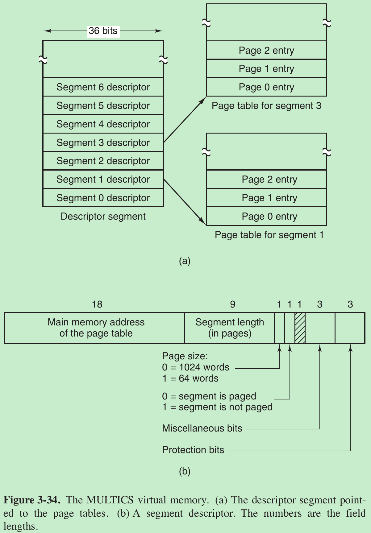
- Because physical addresses were 24 bits and pages were aligned on 64-byte boundaries (implying that the low-order 6 bits of page addresses were 000000), only 18 bits were needed in the descriptor to store a page table address. The descriptor also contained the segment size, the protection bits, and other items. Figure 3-34(b) illustrates a segment descriptor.
- The address of the segment in secondary memory was not in the segment descriptor but in another table used by the segment fault handler.
- Each segment was an ordinary virtual address space and was paged in the same way as the non-segmented paged memory described earlier in this chapter. The normal page size was 1024 words (although a few small segments used by MULTICS itself were not paged or were paged in units of 64 words to save physical memory).
- An address in MULTICS consisted of two parts: the segment and the address within the segment.
- The address within the segment was divided into a page number and a word within the page, as shown in Fig. 3-35.

- When a memory reference occurred, the following algorithm was carried out.
- The segment number was used to find the segment descriptor.
- A check was made to see if the segment’s page table was in memory. If it was, it was located. If it was not, a segment fault occurred. If there was a protection violation, a fault (trap) occurred.
- The page table entry for the requested virtual page was examined. If the page itself was not in memory, a page fault was triggered. If it was in memory, the main-memory address of the start of the page was extracted from the page table entry.
- The offset was added to the page origin to give the main memory address where the word was located.
- The read or store finally took place.

- A register (the descriptor base register) was used to locate the descriptor segment’s page table, which in turn pointed to the pages of the descriptor segment. Once the descriptor for the needed segment was been found, the addressing proceeded as shown in Fig. 3-36.

- The MULTICS hardware contained a 16-word high-speed TLB that could search all its entries in parallel for a given key. It is illustrated in Fig. 3-37. When an address was presented to the computer, the addressing hardware first checked to see if the virtual address was in the TLB. If so, it got the page frame number directly from the TLB and formed the actual address of the referenced word without having to look in the descriptor segment or page table.
- The addresses of the 16 most recently referenced pages were kept in the TLB. Programs whose working set was smaller than the TLB size came to equilibrium with the addresses of the entire working set in the TLB and therefore ran efficiently; otherwise, there were TLB faults.
3.7.3 Segmentation with Paging: The Intel x86
- The heart of the x86 virtual memory consists of two tables, called the LDT (Local Descriptor Table) and the GDT (Global Descriptor Table). Each program has its own LDT, but there is a single GDT, shared by all the programs on the computer.
- The LDT describes segments local to each program, including its code, data, stack, and so on, whereas the GDT describes system segments, including the operating system itself.
- To access a segment, an x86 program first loads a selector for that segment into one of the machine’s six segment registers. During execution, the CS register holds the selector for the code segment and the DS register holds the selector for the data segment. The other segment registers are less important. Each selector is a 16-bit number, as shown in Fig. 3-38.

- One bit tells whether the segment is local or global (i.e., whether it is in the LDT or GDT).
- Thirteen bits specify the LDT or GDT entry number, so these tables are each restricted to holding 8K segment descriptors.
- The other 2 bits relate to protection. Descriptor 0 is forbidden. It may be safely loaded into a segment register to indicate that the segment register is not currently available. It causes a trap if used.
- At the time a selector is loaded into a segment register, the corresponding descriptor is fetched from the LDT or GDT and stored in microprogram registers, so it can be accessed quickly.

- The format of the selector makes locate the descriptor easy. First either the LDT or GDT is selected based on selector bit. Then the selector is copied to an internal scratch register, and the 3 low-order bits set to 0. Finally, the address of either the LDT or GDT table is added to it, to give a direct pointer to the descriptor. For example, selector 72 refers to entry 9 in the GDT, which is located at address GDT + 72.
Trace the steps how a (selector, offset) pair is converted to a physical address
- As soon as the microprogram knows which segment register is being used, it can find the complete descriptor corresponding to that selector in its internal registers. If the segment does not exist (selector 0), or is currently paged out, a trap occurs.
- The hardware then uses the Limit field to check if the offset is beyond the end of the segment, in which case a trap also occurs.
- Logically, there should be a 32-bit field in the descriptor giving the size of the segment, but only 20 bits are available, so a different scheme is used. If the G-bit (Granularity) field is 0, the Limit field is the exact segment size, up to 1 MB. If it is 1, the Limit field gives the segment size in pages instead of bytes. With a page size of 4 KB, 20 bits are enough for segments up to 232 bytes.
- Assuming that the segment is in memory and the offset is in range, the x86 then adds the 32-bit Base field in the descriptor to the offset to form what is called a linear address, as shown in Fig. 3-40.

- The Base field is broken up into three pieces and spread all over the descriptor for compatibility with the 286, in which the Base is only 24 bits. In effect, the Base field allows each segment to start at an arbitrary place within the 32-bit linear address space.
- If paging is disabled (by a bit in a global control register), the linear address is interpreted as the physical address and sent to the memory for the read or write.
With paging disabled, we have a pure segmentation scheme, with each segment’s base address given in its descriptor. Segments are not prevented from overlapping, probably because it would be too much trouble and take too much time to verify that they were all disjoint. - If paging is enabled, the linear address is interpreted as a virtual address and mapped onto the physical address using page tables. With a 32-bit virtual address and a 4-KB page, a segment might contain 1 million pages, so a two-level mapping is used to reduce the page table size for small segments.
- Each running program has a page directory consisting of 1024 32-bit entries. It is located at an address pointed to by a global register. Each entry in this directory points to a page table also containing 1024 32-bit entries. The page table entries point to page frames. The scheme is shown in Fig. 3-41.

- In Fig. 3-41(a) we see a linear address divided into three fields, Dir, Page, and Offset. The Dir field is used to index into the page directory to locate a pointer to the proper page table. Then the Page field is used as an index into the page table to find the physical address of the page frame. Finally, Offset is added to the address of the page frame to get the physical address of the byte or word needed.
- The page table entries are 32 bits each, 20 of which contain a page frame number. The remaining bits contain access and dirty bits, set by the hardware for the benefit of the operating system, protection bits, and other utility bits.
- Each page table has entries for 1024 4-KB page frames, so a single page table handles 4 megabytes of memory. A segment shorter than 4M will have a page directory with a single entry, a pointer to its one and only page table. In this way, the overhead for short segments is only two pages, instead of the million pages that would be needed in a one-level page table.
- To avoid making repeated references to memory, the x86, like MULTICS, has a small TLB that directly maps the most recently used Dir-Page combinations onto the physical address of the page frame. Only when the current combination is not present in the TLB is the mechanism of Fig. 3-41 actually carried out and the TLB updated. As long as TLB misses are rare, performance is good.
- It is also worth noting that if some application does not need segmentation but is simply content with a single, paged, 32-bit address space, that model is possible. All the segment registers can be set up with the same selector, whose descriptor has Base = 0 and Limit set to the maximum. The instruction offset will then be the linear address, with only a single address space used—in effect, normal paging. In fact, all current operating systems for the x86 work this way. OS/2 was the only one that used the full power of the Intel MMU architecture.
- So why did Intel kill what was a variant of the perfectly good MULTICS memory model that it supported for close to three decades? Probably the main reason is that neither UNIX nor Windows ever used it, even though it was quite efficient because it eliminated system calls, turning them into lightning-fast procedure calls to the relevant address within a protected operating system segment. None of the developers of any UNIX or Windows system wanted to change their memory model to something that was x86 specific because it would break portability to other platforms. Since the software was not using the feature, Intel got tired of wasting chip area to support it and removed it from the 64-bit CPUs.
- All in all, one has to give credit to the x86 designers. Given the conflicting goals of implementing pure paging, pure segmentation, and paged segments, while at the same time being compatible with the 286, and doing all of this efficiently, the resulting design is surprisingly simple and clean.
3.8 RESEARCH ON MEMORY MANAGEMENT
3.9 SUMMARY
Please indicate the source: http://blog.csdn.net/gaoxiangnumber1
Welcome to my github: https://github.com/gaoxiangnumber1
- 3-MEMORY MANAGEMENT
- Memory Management (3) DXE 概括
- Memory Management
- Memory Management
- Memory management
- Memory Management
- Memory management
- Memory Management
- Memory management
- Memory Management
- Memory Management
- memory management
- 8.4 Automatic memory management
- 10.9 Automatic memory management
- c memory management(zz)
- Virtual memory management
- Xen Memory Management
- Inside memory management
- 二叉树的前中后序的非递归遍历算法。
- 初识ReactJS的组件化开发(五):ajax加载评论列表,并定时获取更新
- 微信公众号开发(1)
- for循环中break与i++执行
- HDU-n皇后
- 3-MEMORY MANAGEMENT
- 河南多校大一训练赛 frog(拓展欧几里得)
- 多线程
- 矩阵总结
- java夯实基础系列:装箱、拆箱
- Android OSM无法加载地图
- Kindeditor 使用方法及ThinkPHP图片上传
- JavaScript基础
- Caffe CPU训练模型