LTE基础:LTE网络中的IP地址分配
来源:互联网 发布:陀螺 知乎 编辑:程序博客网 时间:2024/06/13 06:50
LTE网络全IP化,数据均在IP包内传输。当UE连接LTE网络,为了和PDN(Packet Data Network)建立连接,一个PDN地址会分配给UE,同时,会在UE和P-GW之间建立默认承载(default bearer),默认承载会保持连接直到UE分离(detach)LTE网络。
LTE网络为每一个用户APN建立默认承载,为每一个APN分配一个唯一的IP地址,这些IP地址可以是IPv4,IPv6,或者IPv4/IPv6类型。
本文将介绍当UE附着网络时,LTE如何为用户分配IP地址?
IP地址分配的类型
当UE initial Attach LTE网络,它请求一个PDN连接,为此,P-GW会分配一个IP地址给UE,并在默认承载建立的同时将IP地址传送给UE。有了这个IP地址,UE才能使用通过PDN提供的服务。
P-GW分配两种类型IP地址:动态和静态IP地址。动态IP地址下,UE每次接入网络,系统会自动分配一个IP地址给UE。静态IP地址下,每一次会分配一指定的IP地址。
动态IP分配
网络首先在P-GW提供一个IP池(IP pool),当UE initial Attach LTE网络,PGW会动态分配一个IP地址给UE。
静态IP地址分配
网络会分配一个永久的IP地址给UE,用户的静态IP信息存储在HSS(Home Subscriber Server,用户归属地服务器),当UE initial Attach网络,P-GW从HSS获取UE静态IP地址,并转发给UE。
动态IP地址分配
流程如下(点击放大看):
P-GW IP分配
在P-GW,会提供一个包含IP地址的IP pool,以及DNS服务器IP地址。
1. [UE ->MME] Requesting for PDN(internet)Connectivity
UE发送 PDN Connectivity Request (PDN type=IPv4,PCO=DNS Server IPv4 Address Request)消息到MME,请求一个UE的IPv4地址和DNS 服务器IP地址(通过PCO域)。PDN Connectivity Request是一个ESM消息,该消息包含在Attach Request的ESM Message container内。
2~3. [MME->S-GW->P-GW] Requesting for Session Creation
MME从HSS获取用户属性(subscription profile),发送 Create Session Request(IMSI,PDN Type=IPv4,PDN Adress=0.0.0.0,PCO=DNS Server IPv4 Address Request)消息到P-GW。因为这是动态IP地址分配,用户信息并不包含IP地址。在Create Session Request消息中,PDN地址域设置为0.0.0.0。
4. [P-GW] 分配PDN地址和DNS服务器地址
P-GW检查PDN类型和PDN地址(0.0.0.0),知道需要分配IPv4地址,它从IPv4 pool里选择一个IP 地址(比如:UE IP=1.1.1.5)分配给UE。同时相应分配DNS服务器地址。
5~6. [MME<-S-GW<-P-GW] Responding to Create Session Request
作为对2~3步骤请求的响应,P-GW发送Create Session Response 消息给MME。这一消息包含了在PDN地址域的UE IP地址(由本地P-GW动态分配)和在PCO域的DNS服务器地址。
7. [UE<-MME] Requesting for Activation of Default Bearer Context
MME发送UE Activate Default EPS Bearer Context Request (PDN Type=IPv4,PDN Address=UE IP (1.1.1.5),PCO={Primary DNS IP,Secondary DNS IP})消息以激活默认承载内容。这一EMS消息包含DNS服务器IP地址和UE IP地址,当传送时嵌入Attach Accept消息内。
8. [UE] Obtaining Dynamic IP Address for using PDN service
UE获得动态IP地址(1.1.1.5)和DNS 服务器IP地址(Primary DNS IP=10.1.1.1,Secondary DNS IP=10.1.1.2)。默认承载在UE和P-GW间建立。UE现在可以连接PDN(internet),可以通过自己的动态IP地址使用internet服务。
静态IP地址分配
流程如下(点击放大):
HSS
HSS提供每个用户的用户属性(subscription profile),这些属性信息包括用于PDN连接的PDN类型和PDN地址。
P-GW
P-GW已设置好DNS服务器IP地址
当用户开机,UE开始initial Attach LTE网络。
1. [UE->MME] Requesting for PDN(Internet) Connectivity
UE发送 PDN Connectivity Request (PDN type=IPv4,PCO=DNS Server IPv4 Address Request)消息到MME,请求一个UE的IPv4地址和DNS 服务器IP地址(通过PCO域)。
2. [MME->HSS] Requesting the LTE Network for Registration
MME发送Update Location Request 消息通知HSS,MME1下有UE请求注册LTE网络。
3. [MME<-HSS] Forwarding Subscription Profile
HSS确认UE在MME1注册后,通过Update Location Answer(IMSI,PDN Type=IPv4,PDN Address = Static UE IP(1.1.1.1))消息发送UE 用户属性到MME1 。这一用户属性中包含了分配给UE的静态IP地址。
4~5. [MME->S-GW->P-GW] Requesting for Session Creation
当MME从HSS接收到用户属性后,MME知道了UE的静态IP地址(1.1.1.1)。MME准备Create Session Request(IMSI,PDN Type=IPv4,PDN Adress=Static UE IP(1.1.1.1),PCO=DNS Server IPv4 Address Request)消息,并发送到P-GW。这一消息包含了在PDN域的静态IP地址。
6~7. [MME<-S-GW<-P-GW] Responding to Create Session Request
作为对4~5步骤请求的响应,P-GW发送Create Session Response (IMSI,PDN Type=IPv4,PDN Adress=Static UE IP(1.1.1.1),PCO={Primary DNS IP,Secondary DNS IP})消息给MME。这一消息包含在PDN地址域的静态UE IP地址和在PCO域的DNS服务器IP地址。
8. [UE<-MME] Requesting for Activation of Default Bearer Context
MME发送UE Activate Default EPS Bearer Context Request (PDN Type=IPv4,PDN Address=Static UE IP(1.1.1.1),PCO={Primary DNS IP,Secondary DNS IP})消息以激活默认承载内容。这一EMS消息包含DNS服务器IP地址和UE IP地址(1.1.1.1),当传送时嵌入Attach Accept消息内。
9. [UE] Obtaining Dynamic IP Address for using PDN service
UE获得静态IP地址(1.1.1.1)和DNS 服务器IP地址(Primary DNS IP=10.1.1.1,Secondary DNS IP=10.1.1.2)。默认承载在UE和P-GW间建立。UE现在可以连接PDN(internet),可以通过自己的静态IP地址使用internet服务。
当用户完成有效网络注册后,PDN地址(IP地址)和默认承载会一直保留给用户,即使用户不在使用Internet服务,这叫为用户提供“always-on IP connectivity”。
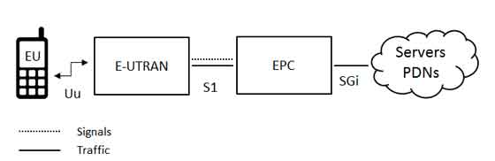
The high-level network architecture of LTE is comprised of following three main components:
The User Equipment (UE).
The Evolved UMTS Terrestrial Radio Access Network (E-UTRAN).
The Evolved Packet Core (EPC).
The evolved packet core communicates with packet data networks in the outside world such as the internet, private corporate networks or the IP multimedia subsystem. The interfaces between the different parts of the system are denoted Uu, S1 and SGi as shown below:
The User Equipment (UE)
The internal architecture of the user equipment for LTE is identical to the one used by UMTS and GSM which is actually a Mobile Equipment (ME). The mobile equipment comprised of the following important modules:
Mobile Termination (MT) : This handles all the communication functions.
Terminal Equipment (TE) : This terminates the data streams.
Universal Integrated Circuit Card (UICC) : This is also known as the SIM card for LTE equipments. It runs an application known as the Universal Subscriber Identity Module (USIM).
A USIM stores user-specific data very similar to 3G SIM card. This keeps information about the user's phone number, home network identity and security keys etc.
The E-UTRAN (The access network)
The architecture of evolved UMTS Terrestrial Radio Access Network (E-UTRAN) has been illustrated below.
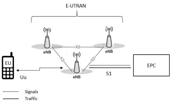
The E-UTRAN handles the radio communications between the mobile and the evolved packet core and just has one component, the evolved base stations, calledeNodeB or eNB. Each eNB is a base station that controls the mobiles in one or more cells. The base station that is communicating with a mobile is known as its serving eNB.
LTE Mobile communicates with just one base station and one cell at a time and there are following two main functions supported by eNB:
The eBN sends and receives radio transmissions to all the mobiles using the analogue and digital signal processing functions of the LTE air interface.
The eNB controls the low-level operation of all its mobiles, by sending them signalling messages such as handover commands.
Each eBN connects with the EPC by means of the S1 interface and it can also be connected to nearby base stations by the X2 interface, which is mainly used for signalling and packet forwarding during handover.
A home eNB (HeNB) is a base station that has been purchased by a user to provide femtocell coverage within the home. A home eNB belongs to a closed subscriber group (CSG) and can only be accessed by mobiles with a USIM that also belongs to the closed subscriber group.
The Evolved Packet Core (EPC) (The core network)
The architecture of Evolved Packet Core (EPC) has been illustrated below. There are few more components which have not been shown in the diagram to keep it simple. These components are like the Earthquake and Tsunami Warning System (ETWS), the Equipment Identity Register (EIR) and Policy Control and Charging Rules Function (PCRF).
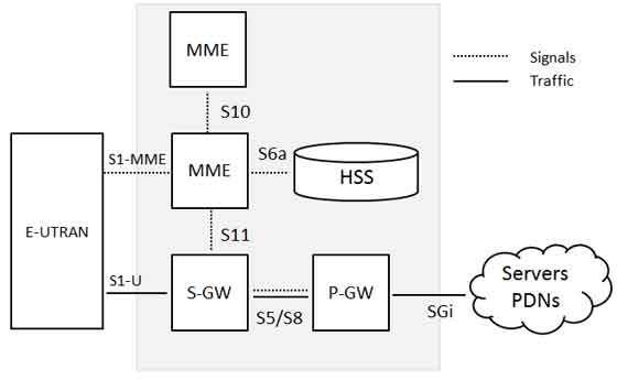
Below is a brief description of each of the components shown in the above architecture:
The Home Subscriber Server (HSS) component has been carried forward from UMTS and GSM and is a central database that contains information about all the network operator's subscribers.
The Packet Data Network (PDN) Gateway (P-GW) communicates with the outside world ie. packet data networks PDN, using SGi interface. Each packet data network is identified by an access point name (APN). The PDN gateway has the same role as the GPRS support node (GGSN) and the serving GPRS support node (SGSN) with UMTS and GSM.
The serving gateway (S-GW) acts as a router, and forwards data between the base station and the PDN gateway.
The mobility management entity (MME) controls the high-level operation of the mobile by means of signalling messages and Home Subscriber Server (HSS).
The Policy Control and Charging Rules Function (PCRF) is a component which is not shown in the above diagram but it is responsible for policy control decision-making, as well as for controlling the flow-based charging functionalities in the Policy Control Enforcement Function (PCEF), which resides in the P-GW.
The interface between the serving and PDN gateways is known as S5/S8. This has two slightly different implementations, namely S5 if the two devices are in the same network, and S8 if they are in different networks.
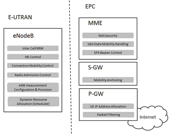
Functional split between the E-UTRAN and the EPC
Following diagram shows the functional split between the E-UTRAN and the EPC for an LTE network:
2G/3G Versus LTE
Following table compares various important Network Elements & Signaling protocols used in 2G/3G abd LTE.
- LTE基础:LTE网络中的IP地址分配
- LTE 网络基础总结
- LTE 中的基础概念
- LTE基础知识之网络基础
- LTE
- LTE
- LTE
- LTE
- LTE
- LTE
- LTE
- LTE
- LTE资源分配
- LTE 频段分配
- 网络演进中的LTE短信解决方案研究
- (5) 网络规划中的IP地址分配
- 网络规划中的IP地址分配
- 网络规划中的IP地址分配
- Proguard中optimize设置不当引发SimException
- 算法训练 出现次数最多的整数
- App 冷启动:给 Android 的 Activity 添加一个背景
- k近邻分类(kNN)
- Git使用说明--常用命令
- LTE基础:LTE网络中的IP地址分配
- ActiveMQ学习教程
- 如何快速学习新的知识
- MongoDB 基础入门
- jquery改变元素属性值
- linux安装中文输入法
- 关于JDBC连接MYSQL的操作问题
- 【Inno Setup】颜色
- 异常的总结